background image

© KROHNE 07/00

7.02230.31.00

Variable area flowmeters
Vortex flowmeters
Flow controllers
Electromagnetic flowmeters
Ultrasonic flowmeters
Mass flowmeters

Level measuring instruments

Communications technology
Engineering systems & solutions

Installation and operating instructions

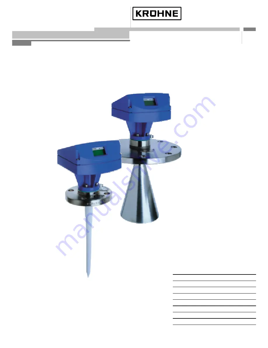
Level-Radar

BM 702

Summary of Contents for BM 702

Page 1: ...eters Vortex flowmeters Flow controllers Electromagnetic flowmeters Ultrasonic flowmeters Mass flowmeters Level measuring instruments Communications technology Engineering systems solutions Installation and operating instructions Level Radar BM 702 ...

Page 2: ...struction Win95 98 NT PC CAT Win 4 00 Online help First series version for BM 702 Items included with supply The scope of supply includes in the version as ordered Signal converter bolted to waveguide window and antenna optionally antenna extension sunshade with fastening material in each case Shielding material with tightening strap not for the US market Installation and operating instructions pl...

Page 3: ...cal codes and regulations apply to its use in hazardous areas Responsibility as to suitability and intended use of these level gauges rests solely with the user Improper installation and operation of our level gauges may lead to loss of warranty In addition the General conditions of sale form the basis of the purchasing contract If you need to return the level gauge to the manufacturer or supplier...

Page 4: ... 8 kpm 5 8 ft lbf Note Ensure the upper Teflon plug is kept absolutely dry and clean Moisture and dirt will impair functionability of the BM 702 Bolt antenna extension to the antenna torque for the 3 stud bolts A max 8 Nm 0 8 kpm 5 8 ft lbf Do not detach bolts H distance piece for high temperature version up to 250 C 482 F upper Teflon plug O ring lower Teflon plug O ring BM70 A connecting flange ...

Page 5: ...the approval certificates Safety Check material compatibility of antenna extension flange gaskets and PP or PTFE used in all versions with the product See also section 8 Type code Mounting on the tank nozzle a Devices with horn antenna The antenna should project out of the nozzle If necessary use an antenna extension Exception in case of a symmetrical tank fitting Tank nozzle Tank nozzle Antenna e...

Page 6: ...nd secure with strap retainer S both items included with supply Strap retainer S must fit closely and overlap both flanges only required for European radio approvals Tighten down stud bolt nuts firmly The tightening torque is dependent upon the strength properties of the stud bolts and the pressure rating of the tank C shielding strip B BM 702 flange S strap retainer F tank flange Positioning on t...

Page 7: ... BM 702 Ex can be incorporated in the PA equipotential bonding system e g by using the separate U clamp terminal at the neck of the BM 702 Ex Rated temperature of connecting cables see Section 6 Supply voltage at the terminals 1 2 The 4 20 mA supply must be able to provide the following voltage U at the terminals of the BM 702 dependent on the current I Please consider also the line resistance and...

Page 8: ...PC Connect the non intrinsically safe side of the isolation amplifier over a load between 120 Ω and 350 Ω to the Smart adapter delivered together with PC CAT and connect it with a serial port of the PC The used isolation amplifier must be HART compatible Local display optional 1 Numeric display measured values 2 Alphanumeric display function unit 3 6 Markers to display measurement status 4 4 keys ...

Page 9: ...th local display The 6 markers x below the local display only show information about the status of measurement and are no error displays 1 No current measured value The device is searching for a new value If the search for a plausible level fails for a certain time SIGNAL DOWN appears as error display 2 Signal too strong Mean of reflected microwaves is very high Gain is automa tically stepped down...

Page 10: ...gain 7 If this value shall not be stored abort by Or accept this 4mA scaling by pressing SURE YES and then 8 Fill the tank to the 100 mark Use the same procedure for the 100 point 20 mA only now by pressing the top keys and 1 2 9 First the measured distance can be taken as block distance After this you can enter or adjust the 20 mA point 100 according to the actual level 1 This example was written...

Page 11: ... mA 22 mA Output of selected value to the current output With safety query 2 4 FIRMWARE 2 4 1 MASTER Display Display of master firmware version 3 0 INSTALL 3 1 BASIS PARAM 3 1 1 TANKHEIGHT Select unit m cm mm inch Ft Enter 0 50 20 00 m Enter tank height see explanatory notes The unit entered here is also used for all other length entries 3 1 2 BLOCKDIST Enter 0 10 m tank height Enter block distanc...

Page 12: ...unit for the conversion table 3 2 5 ERROR MSG Select NO YES Select whether error messages to be shown in display 3 3 SIGNAL OUT 3 3 1 FUNCTION I Select OFF LEVEL DISTANCE CONVERSION SW OUTP Select function of the current output 3 3 2 RANGE I Select 4 20mA 4 20mA E3 6 4 20mA E22 Select range error status for the current output hold last value or 3 6 mA 22mA in error status 3 3 3 SCALE 4mA Enter 200...

Page 13: ...T Value 1 10 100 s Enter time constant for measured value filtering 3 5 4 TRACING VEL Value 0 01 0 50 10 00 m Min Enter the maximum rate of change in level that can occur in operation 3 5 5 MULT REFL Select NO YES Switch the multi reflection identifier on off 3 5 6 BD DETECT Select NO YES Switch the block distance overfill identifier on off see explanatory notes 3 5 7 FUNCT FTB Select OFF PARTIAL ...

Page 14: ... TANKH Before confirming check carefully that the proposed tank height is plausible Block distance The block distance function Fct 3 1 2 defines a zone below the top reference point in which measurements are not meant to take place The value should be at least 10 20 cm greater than the length of antenna antenna extension or at least 20 cm in the case of the Wave Stick Signals within the block dist...

Page 15: ...pletely empty and all moving parts e g agitators switched on If major interference through internals is not expected recording of the empty tank spectrum can also be dispensed with since the factory has already carried out and stored a partial empty spectrum of the flange system Empty tank spectrum recording via display After selecting menu item Fct 3 5 2 press key The display then shows whether t...

Page 16: ...display READY appears after approx 1 3 minutes Then press key five times to store the recorded empty tank spectrum which is taken into account for measurements Empty tank spectrum recording via PC CAT Connect the BM 702 and press in the display mode of PC CAT the key combination Ctrl L The type of empty tank spectrum can be selected by one of the following keys 1 Max Values 4 Max Partial A Break 2...

Page 17: ...00 m Enter block distance 0 60 m 0 6000 m Confirm block distance and move to current output configuration Fct 3 3 SIGNAL OUT Move to lower range value Fct 3 3 3 SCALE 4 mA Display default value 00 000 m Enter lower range value 0 4 m 4 mA 3x 4x 00 400 m Confirm lower range value and move to full scale range value Fct 3 3 4 SCALE 20mA Display of default value 010 00 m Enter full scale value 4 0 m 20...

Page 18: ...read of the covers on the terminal and electronic compartments is well greased at all times distance piece for hightemperature version up to 250 C 482 F O ring BM70 connecting flange signal converter M H Returning a BM 702 The party returning a device is obligated to check and ensure that all cavities in the device are free from dangerous substances toxic caustic flammable water endangering and th...

Page 19: ...65 before mounting dismantling or making electrical connections in a hazardous area Temperature rating of connecting cables The temperature rating of connecting cables is dependent on the maximum temperature of the flange Version Max flange temperature Cable temperature rating Without high temperature 100 C 212 F 70 C 158 F distance piece 100 C 212 F 80 C 176 F With high temperature 200 C 212 F 70...

Page 20: ...50 65 80 Tri Clamp 2 3 4 SMS 51 63 76 mm G 1 Max allowable operating pressure 1 bar vacuum to max 64 bar 928 psig depending on version and flange pressure rating see name plate LP flange system with horn antenna Wave Guide or Wave Stick without flange plate 1 bar vacuum to 2 bar 29 psig V96 flange system with horn antenna or Wave Guide Connection nominal dia Flange rated pressure PN 16 PN 25 PN 40...

Page 21: ...verter Tamb 40 C 4 F to 55 C 131 F Microwaves Measuring principle FMCW Radar Frequency range X Band 8 5 9 9 GHz Antenna radiation angle Type 3 8 Type 4 6 Wave Stick 9 Ex i current output HART passive Current 4 20 mA without or with error message 3 6 mA or 22 mA Accuracy and linearity 0 15 TC 100 ppm K clamp voltage 17V I 4 mA 13V I 20 mA Digital communication HART Ambient conditions Environment cl...

Page 22: ...of the parts in contact with the product Series V96 Antennas and flanges SS Flange and antenna of stainless steel used material see marking on flange HB Flange plating and antenna of Hastelloy B e g B2 used material see marking on plating HC Flange plating and antenna of Hastelloy C e g C4 or C22 used material see marking on plating Ti Flange plating and antenna of Titanium Ta Flange plating and a...

Page 23: ...ve Stick LPTFE or PTFE with Metaglass 2G equipment category 2 application in Zone 1 Wave Stick PP or PTFE without Metaglass or LP flange system free Without Ex approval e g LP version Limits of temperature at flange Version Minimum flange temperature Maximum flange temperature 1 2 of the type code Standard version Special version with marking 2 4610 at the Metaglass ring Without high temperature d...

Page 24: ...1 3 Antenna 3 1 4 Antenna extension 3 1 5 Distance piece 3 1 6 Stillwell diameter 3 1 7 Reference offset 3 1 8 Tank bottom 3 3 1 Current output function offset 3 3 2 Current output range error 3 3 3 Min current scale 3 5 2 Empty spectrum 3 5 3 Time constant 3 5 4 Tracking speed 3 5 5 Multiple reflections yes no 3 5 6 Block distance ident yes no 3 5 7 Function FTB 3 5 8 Epsilon R 3 5 9 Tank type ...

Reviews: