background image

Kramer Electronics Ltd. 


WP-20CT 

– Principles of Operation 

13 


Maestro Built-in Automation Configuration 

WP-20CT

 built-in Maestro automation enables configuring triggers to simply create a 

sequence of actions that are carried out following trigger activation (see 

Configuring Device 

Automation

 on page 

26

).  

Thanks to out-of-the-box default configuration, 

WP-20CT

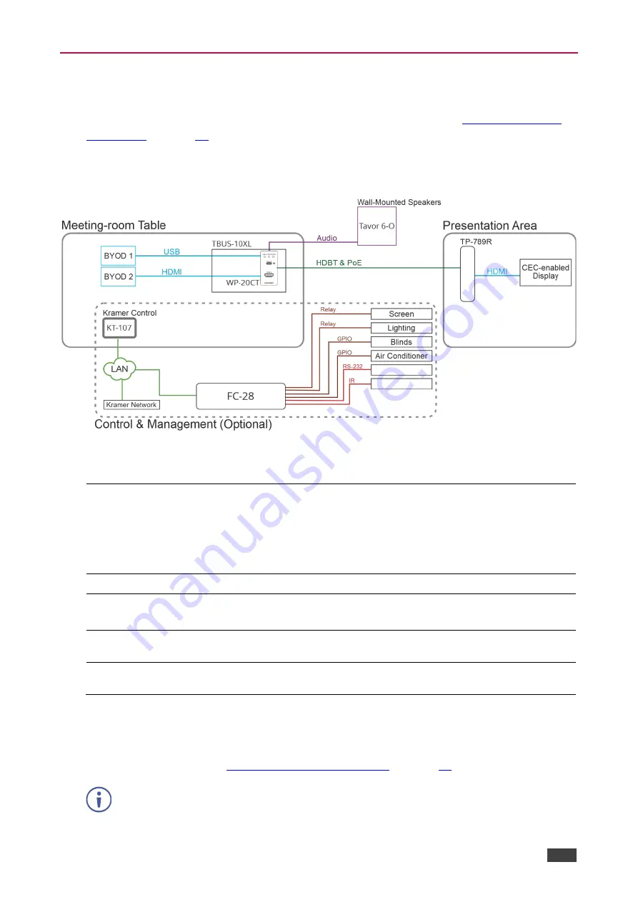
 is ready to control the following 

typical room configuration that can be controlled via several Maestro triggers.  


Figure 7: Typical Room Configuration 

This room includes a meeting-room table, a presentation area, and so on, as follows: 

On the meeting table: 


WP-20CT 

mounted onto a 

TBUS-10XL

 table mount. 

  Various BYOD sources, of which one or two are connected to the 

WP-20CT

 HDMI port (for example, a laptop) and/or the USB-C port 

(for example, a tablet). 

  A 

KT-107

 touch panel supporting Kramer Control controller and 

connected to the LAN. 

On the Wall: 


Tavor 6-O

 wall-mounted speakers connected to 

WP-20CT

In the presentation 
area: 


TP-789R

 receiver, connected via HDBT to 

WP-20CT

  A CEC-enabled display connected to the 

TP-789R

 HDMI output. 

In the room: 

  The window blinds, projector screen, lighting, and air conditioning are 

connected to GPIO/relay ports on the 

FC-28

 IP control gateway. 

LAN connections 


KT-107 Kramer Control 

touch panel controller to 

FC-28

 IP control 

gateway and a 

Kramer Network

 management system. 

WP-20CT

, built-in Maestro configuration enables almost immediate control over these 

elements for different scenarios, once all the elements in the room are connected (with 
minimal settings via built-in Maestro automation embedded web pages, such as device-
specific IP addresses, see 

Configuring Device Automation

 on page 

26

). 


KT-107

 and 

FC-28

 (in the optional control and management system) are not included in 

the built-in Maestro configuration, and should be configured separately. 


Summary of Contents for WP-20CT

Page 1: ...P N 2900 301523 Rev 1 www kramerAV com USER MANUAL MODEL WP 20CT Wall Plate HDBaseT Auto Switcher Transmitter...

Page 2: ...Output 17 Turning Off Video Output 18 Configuring Auto Switching Mode 18 Defining Signal Timeout Settings 19 Configuring AV Settings 20 Copying EDID 21 Changing Device Name 22 Setting Auto Standby Del...

Page 3: ...nal quality due to poor matching and elevated noise levels often associated with low quality cables Do not secure the cables in tight bundles or roll the slack into tight coils Avoid interference from...

Page 4: ...liant extension product Simple and Powerful Maestro Room Control Out of the box configured room control for a typical meeting room setup and intuitive user interface enables you to control your meetin...

Page 5: ...ains powering from connected power adapter Cost effective Maintenance and Management Status LED indicators for Power HDMI and HDBaseT ports facilitate easy local maintenance and troubleshooting Local...

Page 6: ...s not connected Blue an active signal is detected on the input Blue flashing the source is connected but an active signal is not detected HDMI LED STATUS LED Off the device is not receiving power Red...

Page 7: ...ply optional HDBT OUT PoE RJ 45 Connector Connect to the HDBaseT IN port on a PoE provider receiver for example TP 789R or a receiver for example TP 580R When WP 20CT is connected to a PoE providing r...

Page 8: ...onment e g maximum ambient temperature air flow is compatible for the device Avoid uneven mechanical loading Appropriate consideration of equipment nameplate ratings should be used for avoiding overlo...

Page 9: ...US D 1 Gang US electrical junction boxes EU 1 Gang in wall junction box with a cut hole diameter of 68mm and depth that can fit in both the device and the connected cables DIN 49073 UK 1 Gang in wall...

Page 10: ...d to the Control RS 232 connector to control WP 20CT and to the EXTD RS 232 connector to control a device on the receiver side via serial communication 4 Connect the HDBaseT OUT connector to the HDBas...

Page 11: ...T pinout using a straight pin to pin cable with RJ 45 connectors For HDBaseT cables it is recommended that the cable ground shielding be connected soldered to the connector shield EIA TIA 568B PIN Wir...

Page 12: ...Figure 3 Figure 3 Local Area Connection Properties Window 4 Highlight Internet Protocol Version 4 TCP IPv4 depending on the requirements of your IT system 5 Click Properties The Internet Protocol Prop...

Page 13: ...tic IP addressing and fill in the IP address and Subnet mask as shown in Figure 6 You can use any IP address in the range 192 168 1 1 to 192 168 1 255 excluding 192 168 1 39 that is provided by your I...

Page 14: ...input by Sending RS 232 serial commands control see Protocol 3000 Commands on page 40 Using the embedded web pages see Browsing WP 20CT Web Pages on page 16 In auto switching mode switching selection...

Page 15: ...panel supporting Kramer Control controller and connected to the LAN On the Wall Tavor 6 O wall mounted speakers connected to WP 20CT In the presentation area TP 789R receiver connected via HDBT to WP...

Page 16: ...runs a series of actions such as unmuting the audio and video outputs turning the display ON via CEC lowering the screen rolling the blinds down etc In this example the display is turned on via the H...

Page 17: ...ng and Adjusting Audio Output on page 17 Turning Off Video Output on page 18 Configuring Auto Switching Mode on page 18 Defining Signal Timeout Settings on page 19 Configuring AV Settings on page 20 C...

Page 18: ...Username default Admin and Password default Admin and click Sign in The Main AV Routing page appears Figure 9 Embedded Web Pages Main AV Routing Page 11 Click the Navigation Pane on the left side of...

Page 19: ...green checkmark in the column next to it To switch an input to the output 1 Go to the Main AV Routing page Figure 10 Main AV Routing Page 2 Click the box next to the input to which you would like to s...

Page 20: ...t On the Main AV Routing page Figure 10 click the video icon under the output name The video output is turned off and the connected display goes blank Click the disabled video icon to turn on the vide...

Page 21: ...switching operation is initiated by the system To define timeout settings 1 Go to the AV Settings Auto switching tab Figure 11 2 Define timing for the following New AV signal When a new AV source is c...

Page 22: ...efault to define the output HDCP setting according to the active input Device Color Depth Follow Output default or Force 8 bit Force RGB on Output Enable or Disable default Device Auto Unmute on volum...

Page 23: ...y an EDID from one of several different sources to the inputs To copy the EDID to the inputs 1 Go to the EDID Management page Figure 13 EDID Management Page 2 Under Step 1 select the EDID source 3 Und...

Page 24: ...ging Device Name WP 20CT enables you to change the DNS name of the device To change the device name 1 Go to the Device Settings General page Figure 14 Device Settings General Page 2 Under General Pref...

Page 25: ...T enables you to export a configuration file that records all current device settings except the switching configuration This file can then be imported to the same or different WP 20CT device to load...

Page 26: ...restores all factory settings including input output definitions switching configuration IP address and password To restart the device Click Restart on the Device Settings General page Figure 14 To pe...

Page 27: ...e 16 Device Settings Time and Date Page Changing Web Pages Access Password To change the password for accessing the embedded web pages 1 Go to the Device Settings Security page Figure 17 Device Settin...

Page 28: ...20CT Kramer Maestro is a powerful software tool that enables you to configure trigger based room control and automation scenarios without the need for complicated programming To use Maestro control an...

Page 29: ...0CT Operating and Controlling WP 20CT 27 Configuring Ports Maestro enables configuring the ports used to control specific room devices For a full list of default ports see Ports List on page 34 Figure...

Page 30: ...commands and also view and edit the default commands see Actions List on page 34 that are device specific Figure 19 Maestro Page Actions List You can add actions by duplicating an action from the list...

Page 31: ...actions You can add commands to an existing script create new scripts or use the available built in scripts see Scripts List on page 35 For example click the Presentation Start script to view its list...

Page 32: ...it to run For example click the built in First On trigger that triggers the Presentation Start script so that when an active input signal is detected the Presentation Start script runs automatically...

Page 33: ...relevant firmware file and follow the instructions Monitoring Device Status Go to the Diagnostics page Status tab to monitor overall device status temperature and input output activity status For Hea...

Page 34: ...view status diagnostics 1 Go to the Diagnostics Status The Diagnostics page appears 2 Click Advanced tab The Advanced tab appears Figure 23 Diagnostics Advanced Tab 3 Under Traffic Counters view the S...

Page 35: ...2K 4K and 3D as specified in HDMI 2 0 Compliance HDCP 2 3 1 4 Extension line Up to 40m 130ft At 4K 60Hz 4 2 0 Up to 70m 230ft At full HD 1080p 60Hz 36bpp Note To achieve specified extension distances...

Page 36: ...nd Automation Settings Ports List Port Name Type Port Properties Port Description Comment CEC TV CEC 0 CEC Broadcast CEC 15 Local serial RS232 2 9600 1 None 8 Local serial port For custom use Device i...

Page 37: ...OUT K Link CEC Broadcast Trigger Presentation Start V Out Unmute A Out Unmute CEC Power On Notify PresentationStart Wait 0sec Device internal Device internal CEC TV HDBT OUT K Link Trigger Presentatio...

Page 38: ...ime turning off active TVs but may cause disruption when running during actual meetings After Office Hours Prescheduled event occurred Meeting End This recommended trigger is NOT included in Maestro d...

Page 39: ...Hz VESA STD 1152 x 864p at 70Hz VESA STD 1280 x 960p at 60Hz VESA STD EIA CEA 861 Information Revision number 3 IT underscan Supported Basic audio Supported YCbCr 4 4 4 Not supported YCbCr 4 2 2 Not s...

Page 40: ...1 99 A9 40 61 59 45 59 31 59 71 4A 81 40 02 3A 80 18 71 38 2D 40 58 2C 45 00 A0 5A 00 00 00 1E 00 00 00 FF 00 32 39 35 2D 38 38 33 34 35 30 31 30 30 00 00 00 FC 00 56 53 2D 34 31 31 58 0A 20 20 20 20...

Page 41: ...ix nn Command Parameter CR LF Command parameters Multiple parameters must be separated by a comma In addition multiple parameters can be grouped as a single parameter using brackets and Command chain...

Page 42: ...F CEC command to the HDBaseT port CEC SND 1 1 TV OFF 2 e004 CR CEC GW PORT ACTIVE Set the CEC activation state COMMAND CEC GW PORT ACTIVE direction_type port_format port_index state CR FEEDBACK nn CEC...

Page 43: ..._index CR FEEDBACK nn HDCP STAT io_mode in_index status CR LF io_mode Input Output 0 Input 1 Output io_index Number that indicates the specific number of inputs or outputs based on io_mode 1 HDBaseT O...

Page 44: ...COMMAND RESET CR FEEDBACK nn RESET ok CR LF Reset the device RESET CR SN Get device serial number COMMAND SN CR FEEDBACK nn SN serial_num CR LF serial_num 14 decimal digits factory assigned Get the de...

Page 45: ...enough space for data firmware FPGA ERR_FS_NOT_ENOUGH_SPACE 11 Not enough space file system ERR_FS_FILE_NOT_EXISTS 12 File does not exist ERR_FS_FILE_CANT_CREATED 13 File can t be created ERR_FS_FILE_...

Page 46: ...ized dealer from which it was purchased or any other party authorized to repair Kramer Electronics products this product must be insured during shipment with the insurance and shipping charges prepaid...

Page 47: ...nd a list of Kramer distributors visit our website where updates to this user manual may be found We welcome your questions comments and feedback The terms HDMI HDMI High Definition Multimedia Interfa...

Reviews: