P/N: 2900-301511 Rev 1
www.kramerAV.com
USER MANUAL
MODEL:
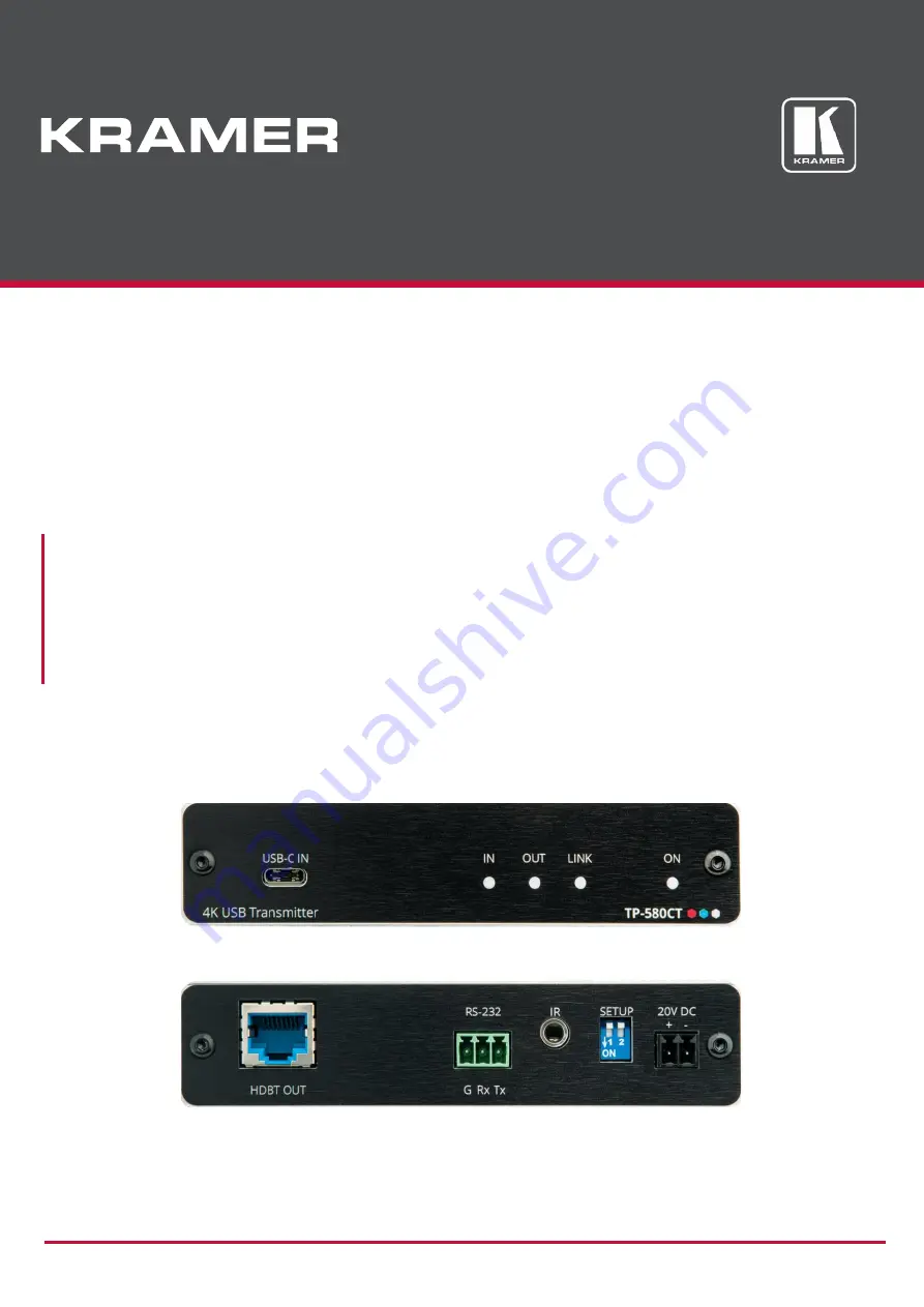
TP-580CT 4K USB Transmitter
Page 1: ...P N 2900 301511 Rev 1 www kramerAV com USER MANUAL MODEL TP 580CT 4K USB Transmitter...
Page 2: ...pical Applications 3 Defining TP 580CT 4K USB Transmitter 4 Mounting TP 580CT 5 Connecting TP 580CT 6 Connecting to TP 580CT via RS 232 7 Wiring RJ 45 Connectors 7 Setting the DIP Switches 7 Powering...
Page 3: ...amer high performance high resolution cables to avoid interference deterioration in signal quality due to poor matching and elevated noise levels often associated with low quality cables Do not secure...
Page 4: ...the transmitted HDBaseT signal It extends video signals to up to 40m 130ft over CAT copper cables at up to 4K 60Hz 4 2 0 24bpp video resolution and provides even further reach for lower HD video resol...
Page 5: ...l interface data flows in both directions allowing data transmission and device control Bidirectional Infrared Extension IR interface data flows in both directions allowing remote control of periphera...
Page 6: ...ce is detected on the receiver side LINK LED Lights green when the HDBT connection is active ON LED Lights green when receiving power HDBT OUT RJ 45 Connector Connects to the HDBT IN RJ 45 connector o...
Page 7: ...flow is compatible for the device Avoid uneven mechanical loading Appropriate consideration of equipment nameplate ratings should be used for avoiding overloading of the circuits Reliable earthing of...
Page 8: ...the HDBT IN port on the receiver side for example Kramer TP 580R 3 On the receiver side TP 580R in this example connect an acceptor for example a display that is connected to the HDMI OUT connector 4...
Page 9: ...rminal block RS 232 Device TP 580CT Wiring RJ 45 Connectors This section defines the HDBT pinout using a straight pin to pin cable with RJ 45 connectors For HDBT cables it is recommended that the cabl...
Page 10: ...80CT is not connected to a power source Charging a USB C Enabled Device A chargeable USB C enabled source that supports at least USB Power Delivery 2 0 that is connected to the USB C IN port can be ch...
Page 11: ...s Rear Panel DIP switches IR output modulation FW Upgrade Indication LEDs Front Panel Input LED Output LED Link LED Power on LED Charging LED Extended IR Frequency 20kHz to 100kHz bi directional Exten...
Page 12: ...ized dealer from which it was purchased or any other party authorized to repair Kramer Electronics products this product must be insured during shipment with the insurance and shipping charges prepaid...
Page 13: ...nd a list of Kramer distributors visit our website where updates to this user manual may be found We welcome your questions comments and feedback The terms HDMI HDMI High Definition Multimedia Interfa...