5
Adapter plate for switch
X1
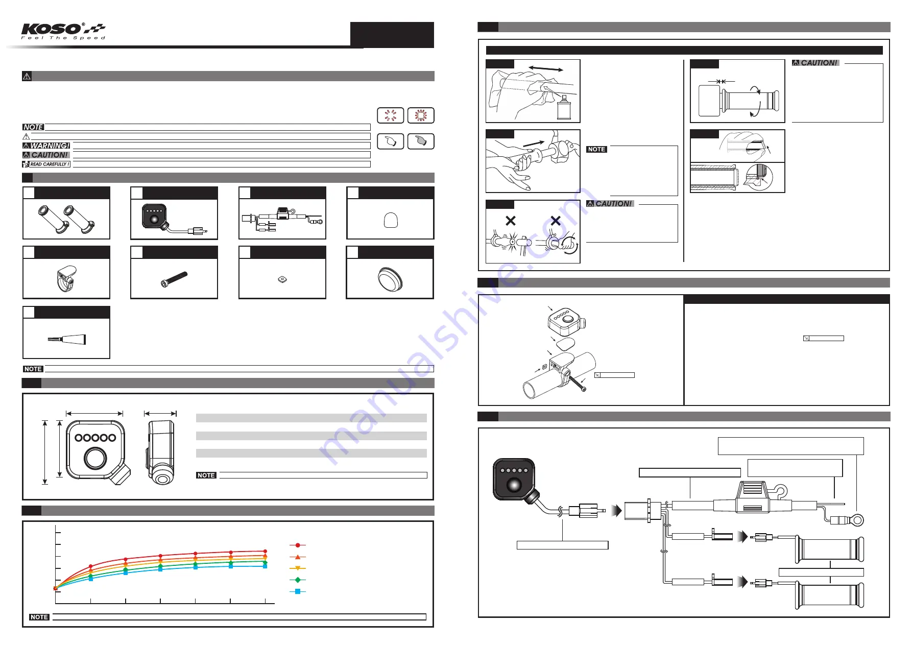
3-3 Wiring installation instructions
wh000axg1a
8
Bar-end cap X2
2
G type switch X1
3
7
M3 nut X1
1
Heated grip X2
4
Velcro X1
9
6
M3XP0.5X25L screw X1
Connecting wire X1
Glue X1
Specifications
2-1
PRESS THE
BUTTON
ONCE
FLASH
LIGHT ON
PRESS THE
BUTTON 3
SECONDS
3.Thrust the heated grip into
the handlebar.
If the heating grip and the
handlebar are under
tighten; then apply the
super glue (Accessory 9)
to strengthen the
tightness to ensure there
will be no twisting during
riding.
To install, please do not use the
tool to knock on or twist to thrust
in the heating grip for thus doing
will break or damage the wire
inside the handlebar.
1.
4.To install the side cap onto
the heating grip, please
insert the top cap into the
top groove and then follow
to push it downward into the
bottom groove.
2.
3-2 Installation instruction
Installation steps
1.G switch (Accessory 2)
Velcro (Accessory 4)
Adapter plate for switch (Accessory 5)
M3XP0.5X25L screw (Accessory 6)
M3 nut (Accessory 7)
2.
3.
4.
5.
0.2 Nm (2 kgf.cm)
0.2 Nm (2 kgf.cm)
3-1 Practical installation instruction
Please proceed as follows
1.
2.
Please use an appropriate
tool to remove the original
handlebar.
Please apply a cleaning
agent and wipe back and
forth to clean away the
residual glue from the
handlebar.
Need to keep cetrain clearace
●
Voltage
●
Switch size
DC 12 V
W38.2 X L38.2 X H16.5 mm
●
Effective temperature range
JIS D 0203
●
Fuse type
4A (ASP)
●
Heating stage
1st stage (low) ~ 5th stage (high)
●
Switch weight (with wire)
About 88 g
Level 1 Temperature Curve
Level 2 Temperature Curve
Level 3 Temperature Curve
Level 4 Temperature Curve
Level 5 Temperature Curve
Heated grip testing data
2-2
2.
1.
3.
5.
4.
34.8 mm
34.8 mm
38.2 mm
16.5 mm
0
0
20
40
60
80
100
120
5
10
15
20
25
30
Design and specifications are subject to change without notice!
Please contact your local distributor if the items received are not the same as the one listed above.
1 Accessories
For installation, please follow the steps described in manual. Any damage caused by wrong installation shall be imputed to the users.
●
Don't break or modify the wire. To avoid the short circuit, please don't pull the wire when installing.
●
Do not disassemble or change any parts excluding the manual description.
●
The interior examination or maintenance should be executed by our professionals.
●
ATTENTION!
●Thank you for purchasing the KOSO heated grips. Before installing, please read the instruction carefully and keep it for future reference.
To install the heating grip onto
the throttle sleeve in right side,
please note that throttle must be
maintained a safe clearance
plus a suitable surplus of wiring;
also they shall be tested by
rotating to and fro for avoiding
interference.
You could get the installation details from the information behind the mark.
Some processes must be followed to avoid the affection caused by wrong installation.
Some processes must be followed to avoid damages to yourself or the public.
Some processes must be followed to avoid the damage to the vehicle.
If any information dealt with in the manual remains unclear seek professional assistance.
◎
MARK MEANING:
Figure 1
Figure 4
Figure 5
Figure 2
Figure 3
Black / Ground wire connect to the vehicle
body or the engine (It must be a good ground)
Red / Positive wire connecting
to the key on switch (DC 12 V)
G type switch (Accessory 2)
Heated grip (Accessory 1)
Connecting wire (Accessory 3)
The testing environment is under 26 Degrees Celsius, with working voltage of 13.5 V.
(Minute)
(
℃
)
INSTRUCTION


