background image

8

Preparations

If you want to process the waveform of a synthesizer or sampler, connect
a mic or the output jack of your external device to the AUDIO INPUT 1
and 2 jacks (

p.29).

○ ○ ○ ○ ○ ○ ○ ○ ○ ○ ○ ○ ○ ○ ○ ○ ○ ○ ○ ○ ○ ○ ○ ○ ○ ○ ○ ○ ○ ○ ○ ○ ○ ○ ○ ○ ○ ○

Connections to MIDI equipment/computers

The keyboard, and controllers etc. of the 

R3

 can be used to control an

external MIDI tone generator. Conversely, another MIDI keyboard or
sequencer can control the tone generator of the 

R3

 to produce sound.

(

p.64)

○ ○ ○ ○ ○ ○ ○ ○ ○ ○ ○ ○ ○ ○ ○ ○ ○ ○ ○ ○ ○ ○ ○ ○ ○ ○ ○ ○ ○ ○ ○ ○ ○ ○ ○ ○ ○ ○

Connecting the included mic

A mic for use with the vocoder is included with the 

R3

. Here's how to

attach the included mic to the 

R3

.

Do not apply excessive force to the neck of the mic, or repeatedly
bend it back and forth any more than necessary. Doing so may cause
malfunctions such as breakage of the internal wiring.

1

Grasp the connector of the mic and con-
nect it to the front panel [MIC] jack. Don’t
use excessive force when plugging it in.

To disconnect the included mic, grasp
the connector and pull it out.

2

Set the [MIC] switch to XLR.

3

Hold down the [SHIFT] button and press
the [VOCODER] button; the input signal from the mic will be output
from the OUTPUT [L/MONO] [R] jack and [PHONES] jack. (This is the
AUDIO IN THRU function.) Hold down the [SHIFT] button and press
the [VOCODER] button once again to return to the normal state.

Be careful of the input and output levels.

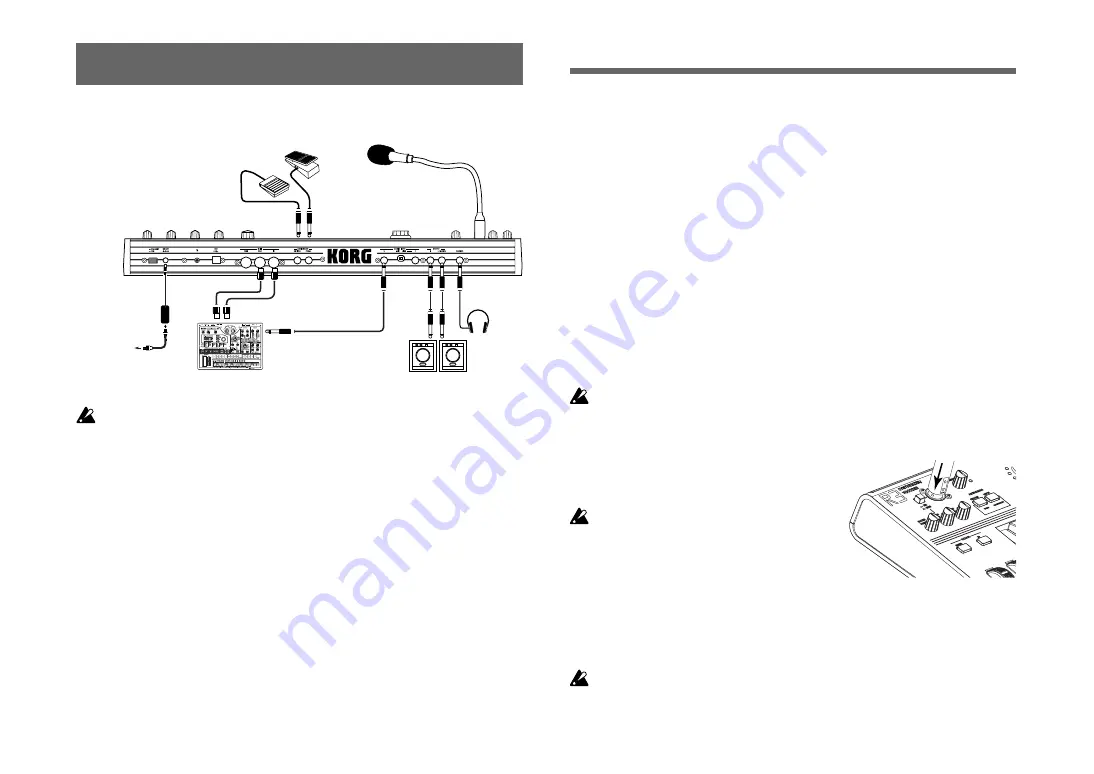
Connections

The diagram below shows basic connections for the 

R3

. Make substitu-

tions as appropriate for your equipment.

MIDI IN

MIDI OUT

Connect to 
an AC outlet

AC adapter 
(included)

Powered monitors, etc.

Phones

MIDI keyboard, tone generator module, 
rhythm machine etc.

Included mic

Be sure to turn off the power of all devices before making connec-
tions. Failing to take this precaution may cause your speaker system
to be damaged, or may cause malfunctions.

○ ○ ○ ○ ○ ○ ○ ○ ○ ○ ○ ○ ○ ○ ○ ○ ○ ○ ○ ○ ○ ○ ○ ○ ○ ○ ○ ○ ○ ○ ○ ○ ○ ○ ○ ○ ○ ○

Connections from the audio outputs

Connect the 

R3

’s OUTPUT [L/MONO] and [R] jacks to the input jacks of

your mixer or powered monitor system.
In order to take full advantage of the potential of the 

R3

, we recommend

that you use stereo outputs.
If you are making monaural connections, use the L/MONO jack.

○ ○ ○ ○ ○ ○ ○ ○ ○ ○ ○ ○ ○ ○ ○ ○ ○ ○ ○ ○ ○ ○ ○ ○ ○ ○ ○ ○ ○ ○ ○ ○ ○ ○ ○ ○ ○ ○

Connections to the audio inputs

If you want to use the 

R3

 as a vocoder, connect a mic or other audio source

to AUDIO INPUT 1, and use that audio source as the modulator (

p.14).

If you want to use an external sequencer, rhythm machine, or audio source
as the carrier of the vocoder, connect that device to AUDIO INPUT 2.

1

2

Summary of Contents for R3

Page 1: ...1 E ...

Page 2: ...ii ...

Page 3: ... particular installation If this equipment does cause harmful interference to radio or television reception which can be determined by turning the equipment off and on the user is encouraged to try to correct the interference by one or more of the following measures Reorient or relocate the receiving antenna Increase the separation between the equipment and receiver Connect the equipment into an o...

Page 4: ...editing procedures 19 Editing each timbre 20 Editing a vocoder program 21 Editing the arpeggiator 22 How to read the pages for each section 22 Introduction 1 Main Features 1 The structure of a program 2 Synthesizer 2 Vocoder 4 Front and rear panel 5 Front panel 5 Rear panel 7 Preparations 8 Connections 8 Connections from the audio outputs 8 Connections to the audio inputs 8 Connections to MIDI equ...

Page 5: ...tion Sequence 47 28 EQ Equalizer 48 29 INSERT FX1 30 INSERT FX2 49 31 MASTER FX 50 Arpeggio parameters 51 Front Panel Arpeggio Parameters 51 32 ARPEGGIATOR A 52 33 ARPEGGIATOR B 53 Vocoder parameters 54 Front panel vocoder parameters 54 34 CARRIER 55 35 MODULATOR A 56 36 MODULATOR B 57 37 FILTER 58 38 FILTER AMP 59 39 CH LEVEL PAN Channel Level Channel Panpot 60 Overall settings GLOBAL 61 GLOBAL s...

Page 6: ...I settings 74 Saving Formant Motion data 74 SHIFT functions 75 Copying and exchanging timbres Initializing a program 75 Initializing Vocoder Parameters 76 Copy Effect 76 Data dump 77 Restoring the factory settings 78 Write protect setting 78 Other SHIFT key functions 79 Index 81 Voice Name List 83 Trouble shooting 86 Specifications and options 87 ...

Page 7: ...the R3 also provides a wide range of oscillator algorithms including formant waves noise and 64 DWGS Digital Waveform Generator System waves With this rich assortment of oscillator algorithms your R3 can produce a vast array of sonic variations 2 Advanced Formant Motion vocoding The R3 includes a sixteen band vocoder In addition to simulating the classic talking instrument vocoder sounds of yester...

Page 8: ...odulation can be applied to the analog synthesizer waveforms of Oscillator 1 Oscillator 2 can be used as the modulating oscillator for the sync modulation SYNC or ring modulation RING that are such classic analog synthesizer techniques The best elements of SYNC and RING modulation can be combined using a third option RING SYNC Voice Unison Pitch These sections provides additional parameters relati...

Page 9: ...er time in a manner similar to vintage analog synthesizers The modulation sequence can play once repeat loop front to back etc providing movement and complexity to the sound The value can change abruptly at each step or it can smoothly transition from value to value The value of each step can be set using the front panel knobs or by using the Motion Rec function to record knob movements changes in...

Page 10: ...e second set is used to apply the same characteristics to another sound the Carrier Each analysis band contains a bandpass filter and an envelope follower Each synthesis band contains a band pass filter whose output is controlled by the matching envelope follower in the analysis band The modulator s audio signal is sent through the sixteen bandpass filters the analysis filters and the envelope fol...

Page 11: ...utton and press one of these buttons to access the corre sponding utility function p 75 SHIFT function TIMBRE SELECT TIMBRE1 TIMBRE1 SOLO TIMBRE2 TIMBRE 2 SOLO buttons Select the timbre s that you want to play or edit You can solo each timbre by holding down the SHIFT button and pressing one of these buttons MIC switch Selects the audio input source for AUDIO INPUT 1 Select the XLR set ting if you...

Page 12: ...ta This lets you produce a vocoder effect without inputting an audio signal from an external source p 18 If this button is dark off a vocod er effect will be produced using an external audio signal By holding down the SHIFT button and pressing this button you can specify the functions that the 1 4 knobs will have in Play mode p 75 SHIFT functions Main display In Play mode this shows information ab...

Page 13: ...you ve connected a mic to the AUDIO INPUT 1 or to the LINE position if you ve connected an external synthesizer or audio device In some cases noise may occur when you operate this switch Turn the MASTER VOLUME knob all the way toward the left before you operate the switch AUDIO INPUT 2 jack For synthesizer programs you can connect an external synthesizer or audio device to this jack and use its au...

Page 14: ...UTPUT L MONO R jack and PHONES jack This is the AUDIO IN THRU function Hold down the SHIFT button and press the VOCODER button once again to return to the normal state Be careful of the input and output levels Connections The diagram below shows basic connections for the R3 Make substitu tions as appropriate for your equipment MIDI IN MIDI OUT Connect to an AC outlet AC adapter included Powered mo...

Page 15: ...able pedal is Expres sion Exp Pedal p 73 ASSIGNABLE SWITCH jack This jack is used for a switch type of pedal such as the Korg PS 1 pedal switch or Korg DS 1H damper pedal The foot switch can be used for various functions including switching programs changing octaves or turning portamento or the arpeggiator on off The pedal can be set to act as a momentary pedal or as a toggle type of switch pedal ...

Page 16: ...your monitor system or other connected output device 1 Turn the R3 s MASTER VOLUME knob all the way toward the left 2 Press the POWER STANDBY switch to turn on the power The display will indicate the program number and name 3 Turn the R3 s MASTER VOLUME knob toward the right to an ap propriate position 4 Adjust the volume of your external output device 1 4 2 3 Turning the power off After saving an...

Page 17: ...en to the demo songs hold down the SHIFT button and press the ARPEGGIATOR ON OFF button The demo will begin playing the PROGRAM NUMBER button will light and the ARPEGGIATOR ON OFF button will blink 2 To switch demo songs during playback press the PROGRAM NUM BER 1 8 buttons 3 When you press the SHIFT button demo playback will stop The R3 will return to normal playing mode 2 1 3 1 ...

Page 18: ...set to the following parameters Timbre 1 Timbre 2 Knob 1 Filter1 Cutoff Frequency Cutoff1 Knob 2 Filter1 Resonance Amount Reso1 Knob 3 Filter Envelope EG1 Intensity EG1 Int1 Knob 4 Master Effect Dry Wet MFX D W 1 Selecting and playing a program The R3 contains 128 programs For easy selection the programs are arranged into 16 banks A P Each bank contains eight programs To select different programs ...

Page 19: ...C9 UP lit red C5 C8 UP lit orange C4 C7 UP lit green Key operation Press UP key Key operation Press DOWN key C3 C6 dark C2 C5 DOWN lit green C1 C4 DOWN lit orange C0 C3 DOWN lit red Keyboard range Key LED Using the keyboard Keyboard Tracking Keyboard tracking uses the position of the note on the keyboard to affect the sound Normally this is used to brighten the sound as you play upward or to creat...

Page 20: ...er you can speak or sing into a mic and play chords on the keyboard to create the impression that an instrument is speaking or singing You can also create a variety of interesting effects by using audio signals other than a human voice such as rhythm sounds 1 Turn the AUDIO INPUT 1 knob all the way to the left and set the MIC switch to XLR 2 Connect the included mic to the MIC connector p 8 3 Sele...

Page 21: ... on the button will light 3 Hold down a chord on the keyboard and the arpeggiator will run Modifying the arpeggio 4 Turn the PAGE dial and select either the 32 Arpeggiator A or the 33 Arpeggiator B page 5 Turn the knobs 1 4 to adjust the arpeggiator parameters changing the way that the arpeggiator is sounded Adjust the tempo by TEMPO knob 2 4 6 5 Turning individual steps on and off to vary the arp...

Page 22: ...the four Perfor mance Edit knobs 1 Select a synth program 2 Select a timbre by pressing either the TIMBRE1 or TIMBRE2 but ton The button for the selected timbre will blink 3 Turn the modulation sequencer on by pressing the MOD SEQ ON OFF button The button will light 4 Press the MOD SEQ REC button to arm the modulation sequencer for recording 5 While holding down notes on the keyboard turn the knob...

Page 23: ...FF button The button will light 4 Turn the PAGE dial to enter Edit mode and select the page that con tains the parameter you want to record 5 Press the MOD SEQ REC button to arm the modulation sequencer for recording 6 While holding down notes on the keyboard turn one of the knobs 1 4 Recording will begin the moment you turn the knob When you ve reached the last step the REC button will go dark an...

Page 24: ... a changing modulator signal This saved formant motion data can be used to produce vocoder effects without having to vocalize into a mic each time you perform In its internal memory the R3 can store sixteen sets of formant motion data each up to 7 5 seconds long Vocoder programs programs for which the VOCODER button is lit can use this data When the R3 is shipped from the factory bank O FORMANT MO...

Page 25: ...ff frequency knob 2 will adjust the resonance knob 3 will adjust the filter balance and knob 4 controls the filter routing 2 3 Go ahead and try editing the 15 EG2 page ozBameters Attack2 and Decay2 p 41 the 3 Pitch A page parameter Portamnt p 25 or the 29 Insert FX1 page parameter Type to hear the result p 49 4 Repeat steps 2 3 as necessary to create the desired sound 5 Write the program into memo...

Page 26: ...e and turn knob 1 knob to select Layer Selecting the timbre to edit If you are editing a program that uses both timbres here s how to select the timbre to edit Press the TIMBRE SELECT TIMBRE1 button to select timbre 1 as the timbre that you want to edit TIMBRE SELECT TIMBRE1 button will light Your editing will affect the selected timbre Listening to only one timbre Solo For a program that uses bot...

Page 27: ...re 1 Timbre 2 Synth Audio In 1 Synth Vocoder EQ EQ INSERT FX1 2 INSERT FX1 2 MASTER FX Audio In 2 Carrier Modulator OUTPUT L MONO R Vocoder Sw ON Modulator AudioSrc Timbre2 Vocoder Sw ON To input your voice as the modulator turn the front panel FORMANT MOTION ON OFF button off and set the 35 Modula tor A page AudioSrc parameter to Input1 Basic editing Vocoder section The parameters for the sixteen...

Page 28: ...reasing this value may cause distortion Knob 3 Filt1Bal Filter1 Balance LPF24 LPF12 HPF BPF THRU Selects the filter type Intermediate settings will produce a response that is between the two filter types LPF12 12dB oct LPF24 24dB oct Low Pass Filter p35 LFP HPF 12dB oct High Pass Filter p35 HFP BPF 12dB oct Band Pass Filter p35 BFP THRU The sound will output directly without passing through the fi...

Page 29: ...channel Timbre1 will always be set to the Glo bal MIDI channel You can specify the timbre1 MIDI channel by setting the 42 MIDI page parameter MIDI Ch Knob 3 Assign Mono1 Mono2 Poly This parameter specifies how notes will be articulated from the keyboard or MIDI source Mono1 The timbre will play monophoni cally If you continue holding down the key you first pressed the EG will not retrigger when yo...

Page 30: ...tually be sounded Turning on the Unison function will limit the available polyphony Knob 2 Detune Unison Detune 0 99 This parameter is available when Unison is on i e if Sw is 2 4 Voice It specifies in units of cents the amount of detuning that will occur between the stacked voices Regardless of how many voices are stacked this parameter will always specify the total range of detuning 4 voice Unis...

Page 31: ... the pitch of the oscillator in one cent steps Knob 3 AnlgTune Analog Tune 000 127 By adding a slight randomness to the pitch of each note as it is played this parameter can simulate the pitch instability and os cillator drift that was characteristic of analog synthesizers Higher settings will produce greater variations in pitch Knob 4 Portamnt Portamento 000 127 Portamento is a smooth change in p...

Page 32: ...ge of the PITCH wheel in semitones This value specifies the amount of change that will occur when you move the pitch wheel all the way up or all the way down Knob 2 Vib Int Vibrato Intensity 2400 2400 Specifies the depth of vibrato that will be applied when you move the MOD wheel all the up By default LFO2 is the vibrato source for the MOD wheel ...

Page 33: ...he waveform The following parameters Cross Uni son VPM are only available when the Wave parameter is set to is Saw Pulse Tri or Sin and are not available if the WAVE parameter is set to Formant Noise DWGS or AudioIn Cross Cross Modulation Cross Modula tion uses the output waveform of oscillator 2 the modulator to modulate the frequency of oscillator 1 the carrier at high speed to produce a modulat...

Page 34: ...square waves and are suitable for mild tone such as bass or pads Adjust ing the value will modify the shape of the waveform changing the harmonic content A setting of 000 produces a simple triangle wave Higher setting stress different har monics a setting of 127 produces a triangle wave that is one octave and a fifth higher i e the third harmonic 000 063 127 Knob 1 Wave Sine Sine wave is a mild to...

Page 35: ...E dial to the 5 OSC 1 page and set WAVE knob 1 to AudioIn 6 Send an audio signal from the exter nal device and turn the AUDIO IN PUT 1 and AUDIO INPUT2 knob toward MAX as far as possible with out allowing the AUDIO INPUT 1 and AUDIO IN 2 LED to light red MIDI IN MIDI OUT tone generator module rhythm machine or audio device 7 While inputting an audio signal play the keyboard 8 Edit the FILTER AMP E...

Page 36: ...e effect will be easier to detect if you lower OSC 1 Lvl and raise OSC 2 Lvl You can also create in teresting effects by using Virtual Patch to modu late OSC2Tune from LFO or EG Sync This type of modulation forcibly synchro nizes the phase of oscillator 2 to the phase of oscillator 1 and is useful for creating lead synth type sounds Figure 6 2 Knob 3 OSC2Semi Oscillator 2 Semitone 24 24 Specifies ...

Page 37: ...ance as the oscilla tor 1 noise generator does but you can use the FILTER section to create the same re sults as the noise waveform of oscillator 1 Noise is used to create percussion instru ment sounds or sound effects such as surf Knob 4 PunchLvl Punch Level 000 127 Creates a more snappy attack by adjust ing the amount of pulse waveform that is added to the oscillator output only during the attac...

Page 38: ...ri ant change produced by EG1 by key board playing dynamics velocity and by note location keyboard track ing If the Cutoff1 value is set too low the volume may be extremely low or you may hear no sound at all 8 FILTER1 A The filter section changes the tonal character of the oscillators by passing only the desired portion of the sound either above Low Pass below High Pass or centered on Band Pass t...

Page 39: ...gh Pass Filter passes the frequen cies above the cutoff frequency and cuts the region below Use this when you want to make the tone thinner However raising the cutoff frequency too far will drastically reduce the volume HPF High Pass Filter Cutoff Frequency BPF BPF Band Pass Filter passes the frequen cies in the region of the cutoff frequency and cuts all other frequency regions Use this when you ...

Page 40: ... 9 1 EG Intensity Time Note on Note off Cutoff SustainLevel Attack Time Decay Time ReleaseTime Figure 9 2 EG Intensity positive settings Note on Note off Note on Note off Cutoff Int 32 Int 0 Int 63 Time Cutoff frequency specified by Cutoff Figure 9 3 EG Intensity negative settings Cutoff frequency specified by Cutoff Note on Note off Note on Note off Cutoff Int 32 Int 0 Int 63 Time Knob 2 Key Trk1...

Page 41: ...s is the same as for FILTER 1 p 32 Knob 2 Reso2 Filter2 Resonance 000 127 This is the same as for FILTER 1 p 32 Knob 3 Type2 Filter2 Type LPF HPF BPF COMB Selects the filter type LPF HPF BPF These are the same filter type as for filter 1 p 32 COMB In a comb filter so named for its resemblance to the teeth of a comb alter nating bands pass and cut the signal giv ing a unique character to the sound ...

Page 42: ...eters Knob 1 EG1 Int2 EG1 Intensity Filter2 63 63 This is the same as for FILTER 1 p 34 Knob 2 Key Trk2 Keyboard Tracking Filter2 2 00 2 00 This is the same as for FILTER 1 p 34 Knob 3 VelSens2 Velocity Sensitivity Filter2 63 63 This is the same as for FILTER 1 p 34 ...

Page 43: ...right Knob 3 Key Trk Keyboard Tracking 63 63 Specifies how keyboard tracking will af fect the volume With positive settings the volume will increase as you play above the C4 note on the keyboard and will decrease as you play below C4 With negative settings the volume will decrease as you play above the C4 note on the keyboard and will increase as you play below C4 Keyboard Track operates according...

Page 44: ... functions will be applied PreFilt1 Drive or wave shape will be ap plied before filter 1 p 39 Figure 13 9 Pre Amp Drive or wave shape will be ap plied after the filter and before the amp p 39 Figure 13 10 Knob 1 OctSaw Cuts the portion of the waveform above the threshold level and inverts it to keep it within limits p 39 Figure 13 4 MultiTri Sending a sawtooth wave through this will produce a tria...

Page 45: ...64 Depth 127 Figure 13 4 OctSaw Depth 000 Depth 064 Depth 127 Figure 13 5 MultiTri Depth 000 Depth 064 Depth 127 Figure 13 6 MultiSin Depth 000 Depth 064 Depth 127 Figure 13 7 Pickup Depth 000 Depth 064 Depth 127 Figure 13 8 LvlBoost Depth 000 Depth 064 Depth 127 Figure 13 9 Position PreFilt FILTER1 DRIVE WS OSC AMP Figure 13 10 Positon Pre Amp DRIVE WS FILTER1 OSC AMP ...

Page 46: ...ed after the decay time has elapsed until you release the key Knob 4 Release1 Release EG1 000 127 Specifies the time from note off when the key is released until the level reaches 0 Knob 1 Attack1 Attack EG1 000 127 Specifies the time from note on when the key is pressed until the attack level maxi mum value of the envelope is reached Figure 14 1 EG1 envelope 0 AttackLevel Time Note on Note off Cu...

Page 47: ...ue holding the key Knob 4 Release2 Release EG2 000 127 Specifies the time from note off when the key is released until the level reaches 0 EG Envelope Generator To a significant extent each sound has its own distinctive volume curve For example when you play a note on a piano the note begins at the maximum volume and gradually diminishes When you release your finger from the key the sound will dis...

Page 48: ...es the time from note on when the key is pressed until the attack level maxi mum value of the envelope is reached Knob 2 Decay3 Decay EG3 000 127 Specifies the time from when the attack level is reached until the sustain level SUS TAIN is reached Knob 3 Sustain3 Sustain EG3 000 127 Specifies the volume that will be main tained after the decay time has elapsed as long as you continue holding the ke...

Page 49: ... play strongly Negative values The EG amplitude will be less when you play strongly and greater when you play softly Knob 1 EG1 Lvl EG1 Level 63 63 Specifies the amout of change that the ve locity keyboard dynamics will have on EG1 s amplitude level Knob 2 EG2 Lvl EG2 Level 63 63 Specifies the amout of change that the ve locity keyboard dynamics will have on EG2 s amplitude level Knob 3 EG3 Lvl EG...

Page 50: ... this value will result in a faster fre quency This parameter will be displayed and can be set only if BPM Sync is Off SYNC NOTE 8 1 1 64 Specifies the LFO frequency as a note value derived from the tempo specified by the TEMPO knob This parameter is only avail able when BPM Sync is On 8 1 One LFO cycle 32 beats in length 4 1 One LFO cycle 16 beats in length 1 1 One LFO cycle 4 beats in length 1 2...

Page 51: ...page Cutoff1 Reso1 The 8 Filt1 A page Reso1 Cutoff2 The 10 Filt2 A page Cutoff2 WS Depth The 13 Drive WS page WS Depth Level The 12 Amp page Level Panpot The 12 Amp page Panpot LFO1Freq The P18 LFO1 page Freq LFO2Freq The P19 LFO2 page Freq Virtual Patch On modular analog synthesizers the input or output of each module oscillator filter amp EG LFO and other controllers could be connected patched b...

Page 52: ...the value of the last step Knob 3 KeySync Off Timbre Voice Specifies how the sequence will be reset when note on occurs i e when a key is played Off The sequence will not be reset when note on occurs Timbre The sequence will be reset when the first note on occurs for a timbre from a condition of all keys being released In the case of a program for which different re gions of the keyboard play diff...

Page 53: ...ll change when the sequence is played Smooth The change will be continuous with the values recorded at each step con nected by straight lines Step The value recorded at each step will be held until the next step plays If you set Dest to OSC1Ctr2 OSC1 Control 2 when OSC1 Wave is set to DWGS the operation will be the same as Step even if this parameter is set to Smooth Knob 3 Step Select Step 01 Ste...

Page 54: ...equency Knob 3 HiEGFreq High EQ Frequency 1 00Hz 20 0kHz Specifies the cutoff frequency of the high equalizer shelving type 28 EQ Equalizer Here you can adjust the equalizer settings The equalizer is a shelving type Figure 28 1 Knob 4 HiEQGain High EQ Gain 15 0dB 15 0dB Specifies the gain of the high equalizer Positive values boost the region above the cutoff frequency Negative values cut the regi...

Page 55: ...he value of that pa rameter The available parameters will de pend on the effect you choose for Type For details on the available effect types re fer to the Effect Guide in the included CD ROM IFx1Knob IFx2Knob Use knob 4 Value to select the effect parameter you ll control from knobs 1 4 in Play mode p 80 SHIFT function Knob as signment Knob 4 Value This specifies the value of the parameter you sel...

Page 56: ...arameter e g Sens When you use Effect parameter knob 3 to select a pa rameter the display for knob 4 will switch to the value of that parameter The avail able parameters will depend on the effect you choose for Type For details on the available effect types refer to the Effect Guide in the included CD ROM MFx Knob Use knob 4 Value to se lect the effect parameter you ll control from knobs 1 4 in Pl...

Page 57: ...po specified by the TEMPO knob ARPEGGIATOR ON OFF button Switches the arpeggiator on off The but ton will light if this is on ARPEGGIATOR LATCH button Specifies latch operation for the arpeggia tor On buttonlit Thearpeggiatorwillcon tinue playing after you take your hand off the keyboard Off buttondark Thearpeggiatorwill stop playing when you take your hand off the keyboard Front Panel Arpeggio Pa...

Page 58: ...ted The highest and lowest notes will be played once Alt2 UpandDownwillbealternated The highest and lowest notes will be played twice once on the way up and once on the way down Random Notes will be played randomly Trigger The notes you are holding down will be played simultaneously at the tempo and Resolutn timing The OctRange setting will be ignored If you are holding down more notes than the ma...

Page 59: ...ecified tempo 1 12 Thearpeggiowillbeplayedas8th note triplets at the specified tempo 1 8 The arpeggio will be played as 8th notes at the specified tempo 1 6 The arpeggio will be played as quar ter note triplets at the specified tempo 1 4 The arpeggio will be played as quar ter notes at the specified tempo 1 3 The arpeggio will be played as half note triplets at the specified tempo 1 2 The arpeggio...

Page 60: ... s modulator Off key unlit Formant Motion off The audio source selected by AudioSrc is used as the modulator On key lit Formant Motion on Formant motion data is used as the modulator Use the 35 Mod A page to specify how the data is played If this is on the audio source AudioSrc input will automatically be turned off FORMANT MOTION REC button This key lets you record formant motion data for use as ...

Page 61: ...Lvl Timbre1 Level 000 127 Specifies the output level of Timbre1 car rier If you are unable to hear the vocoder effect try adjusting the Tmbr1Lvl parameter or the 38 Filt Amp page Vcd Lvl parameter p 59 Knob 2 Input2Lv Input2 Level 000 127 Specifies the output level of the signal cannected to the AUDIO INPUT2 jack ...

Page 62: ... will play as a loop TrgReset Each time you play the key board the formant motion data will play back from the beginning The formant motion data will be trig gered on the global MIDI channel This has no effect if formant motion is off FORMANT MOTION ON OFF key unlit Knob 3 AudioSrc Audio Source Input1 Timbre2 This selects the audio source that will be input as the modulator When recording formant ...

Page 63: ...be more chance that the audio in put signal itself will be cut making it difficult for you to apply the vocoder effect as intended Knob 3 HPF Gate Disable Enable Specifies whether the high frequency por tion of the signal from AUDIO IN 1 that is mixed into the vocoder output will be passed only during the key on note on duration or will always be allowed to pass Disable The high frequency portion ...

Page 64: ...f the input sig nal to be detected more rapidly If you set this to Hold the character of the signal that is being input at that moment will be held Formant Freeze Subse quently the sound will retain that charac ter regardless of whether there is any in put If you set this to Hold when there is no input signal present there will be no output even if an audio signal is subsequently input If you writ...

Page 65: ... p 45 Source1 Source6 Knob 2 FcModInt Fc Modulation Intensity 63 63 Specifies the depth of the modulation that is applied to the carrier band pass filter Synthesis filter FcOffset Knob 3 DirectLv Direct Level 000 127 Sets the volume level at which the modulatior input source will be output directly unaffected If you press the VOCODER button to make it blink and raise the Edit mode 38 Filt Amp page...

Page 66: ...1 Ch16 Selects one of the sixteen filter channels for editing 39 CH LEVEL PAN Channel Level Channel Panpot These parameters set the level and pan for each of the sixteen band pass filter channels Synthesis Filter of the carrier p 55 Knob 3 Pan1 Pan16 L63 CNT R63 Specifies the panning of the selected chan nel ...

Page 67: ...h of all programs When you are playing the R3 to gether with other instruments use MstTune to match the pitch If you want to transpose the pitch of the song you are playing you can adjust Transpos In cases such as when you use multiple programs in a single song it is convenient to simply adjust the GLOBAL setting instead of adjusting the pitch of each individual pro gram If you want to keep the ch...

Page 68: ...or medium strength playing How ever these curves will also produce a Knob 4 Position Post KBD Pre TG Specifies the internal MIDI IN OUT rout ing within the R3 This setting will affect the way in which MIDI data is transmitted and received and how the arpeggiator data is handled PostKBD Inthisposition incomingMIDI data will be sent to the timbres without being affected by the global or front panelt...

Page 69: ... 2 jackwill be sent to the OUT PUT L MONO and R jacks without change You can use the AUDIO IN THRU function to check whether the signal from each jack is being input correctly This also lets you use the mic to speak to the audience between songs Knob 2 KnobMode Jump Catch Specifies the behavior of the front panel knobs 1 4 and TEMPO knob when editing Jump Whenyouturntheknob theparam eter value wil...

Page 70: ...e a MIDI cable to connect the R3 s MIDI OUT con nector to the MIDI IN connector of the external MIDI tone generator MIDI OUT MIDI IN R3 MIDI tone generator EM 1 TAP 1 2 5 7 10 12 14 16 15 13 11 9 8 4 3 Using the R3 with other MIDI devices MIDI Controlling the R3 s tone generator from an external MIDI device When you wish to play or control the R3 s tone generator from an external MIDI keyboard or ...

Page 71: ...r the MIDI connection or the USB connection does not work you should also check the Routing setting p 68 in the 42 MIDI page MIDI related settings MIDI channel setting In order to exchange data with a connected external MIDI device you must set the R3 s MIDI channel to match the MIDI channel of the external MIDI device 1 Set the MIDI channel of the R3 Select the PAGE dial to the 42 MIDI page and u...

Page 72: ...operate the R3 s knobs and keys to control an external MIDI device Use the 44 MIDI CC page to assign con trol change messages to parameters p 71 MIDI LOCAL setting when connecting an external MIDI sequencer or computer If notes are sounding doubled when the R3 is connected to an external MIDI sequencer or computer turn the Local setting off 42 MIDI page Local Off p 68 If the R3 is connected to an ...

Page 73: ...will operate at the tempo specified by the R3 s TEMPO knob 2 Using the external MIDI device as master and the R3 as slave Connect the R3 s MIDI IN connector to the external MIDI device s MIDI OUT con nector p 64 If you select the PAGE dial to the 42 MIDI page and set 42 MIDI page Clock knob 4 to Ext MIDI the R3 will be the slave The R3 s arpeggiator will operate at the tempo of the external MIDI d...

Page 74: ...nsmit and receive MIDI messages Thru operation via the MIDI IN and MIDI THRU connectors is enabled p 69 Figure 42 2 MIDI Only the MIDI connectors will be used to transmit and receive MIDI messages p 69 Figure 42 3 The Thru function from the MIDI IN to the MIDI THRU connectors is active even if this parameter is set to USB Knob 4 Clock Auto Internal Ext USB Ext MIDI Specifies how the R3 will synchr...

Page 75: ...rt Figure 42 2 USB MIDI OUT MIDI IN MIDI THRU TG OUTPUT DUMP IN etc KBD KNOB OUT DUMP OUT etc USB MIDI RX EXT USB MIDI TX INT USB MIDI TX EXT USB MIDI RX INT R3 MIDI OUT R3 KBD KNOB R3 MIDI IN R3 SOUND R3 PC USB MIDI Port Figure 42 3 MIDI MIDI OUT MIDI IN MIDI THRU TG OUTPUT DUMP IN etc KBD KNOB OUT DUMP OUT etc USB MIDI RX EXT USB MIDI TX INT USB MIDI TX EXT USB MIDI RX INT R3 MIDI OUT R3 KBD KNO...

Page 76: ...Disable MIDIcontrolchangeswillnotbe transmitted or received Enable MIDI control changes will be transmitted and received Knob 3 PitchBnd Pitch Bend Disable Enable Selects whether pitch bend messages will be transmitted and received Disable Pitchbendmessageswillnotbe transmitted or received Enable Pitchbendmessageswillbetrans mitted and received Knob 4 SystemEx System Exclusive Disable Enable Selec...

Page 77: ...ves one of these control change messages the value of the corresponding parameter will change Supplementary material on the CD ROM Control change assignments for the R3 s knobs buttons Knob 1 Parameter Portamnt VcdFmtNo Select the knob or button Knob 2 Value NoAssign CC 000 CC 095 CC 102 CC 119 Assign a MIDI control change number CC for the knob or button selected in Parameter knob 1 If the select...

Page 78: ...ed to modulation sources MIDI 1 of the Vir tual Patch function With the factory set tings MIDI1 is assigned to 016 CC 16 Knob 2 MIDI2 P Bend 119 These select the functions that are assigned to modulation sources MIDI 2 of the Vir tual Patch function With the factory set tings MIDI2 is assigned to 002 CC 02 Knob 3 MIDI3 P Bend 119 These select the functions that are assigned to modulation sources M...

Page 79: ...n of the pedal switch connected to the ASSIGNABLE SWITCH jack With the factory settings this is set to Damper Damper Thepedalswitchwillfunctionas a damper pedal CC 66 ProgUp ProgDown Thepedalswitchwill advance to the program with the next high est increment or next lowest decrement number OctUp OctDown Thepedalswitchwill change the octave Turning the switch on will shift the pitch by 1 1 octave Pr...

Page 80: ...m the type of data to be saved so use the PAGE dial to select Glo bal and then press the WRITE but ton once again 2 Press the WRITE button once again to save write the global data and MIDI settings The main display will indicate Com plete The Write operation is com pleted and you ll return to the Play mode If you press the WRITE button when one of the Edit mode 40 MIDI 46 Pedal Sw pages are select...

Page 81: ...e main dis play will show the name of the currently selected program 2 To initialize the program press the 2 button The program will be initialized and you ll return to Play mode If you decide not to initialize the pro gram press the EXIT button show the copy source program number and timbre and the copy destination timbre 6 To execute the copy press the 3 but ton The settings will be copied and y...

Page 82: ...itialize the vocoder settings press the 3 button The vocoder settings will be initialized and you ll return to Play mode If you decide not to execute the opera tion press the EXIT button The vocoder parameters will also be initialized if you initialize the pro gram Copy Effect 5 1 COPY EFFECT Copy effect setting Here s how to copy the effect settings from another program into a effect of the cur r...

Page 83: ...e R3 s MIDI channel to the same channel setting as when the data was originally transmitted 3 Set the 43 MIDIFilt page SystemEx to Enable turn the Shift function PROTECT to off Data dump Data dump is a function that transmits program or global data in the form of MIDI exclusive data so that it can be saved on a connected MIDI data filer or computer This can also be used to transmit data to another...

Page 84: ...SHIFT button and press the 8 button The main display will show a screen where you can select protect on off 2 Turn the PAGE dial to switch write protect on off 3 When you have made the desired set ting press the lit 8 button or SHIFT button The R3 will return to the Play mode If you decide not to execute the operation press the EXIT button Write protect setting Restoring the factory settings Resto...

Page 85: ...ibration operation press the EXIT button TIMBRE1 SOLO TIMBRE2 SOLO Soloing a timbre For a program that uses two timbres this operation lets you listen to just one of the timbres While editing you can use this when you want to hear a single timbre by itself 1 Hold down the SHIFT button and press the TIMBRE SELECT TIMBRE 1 or TIMBRE 2 button Only the tim bre whose button you press will be heard 2 Ho...

Page 86: ...effect 1 while you re in Play mode Other SHIFT key functions Knob assignments You can assign parameters to knobs 1 4 This lets you control the sound and settings in Play mode while you perform This is referred to as Performance Editing You can make a separate set of knob 1 4 assignments for the Timbre 1 Timbre 2 and Vocoder sections use the TIMBRE SELECT TIMBRE 1 TIMBRE 2 or VO CODER buttons to se...

Page 87: ...1 MOD wheel 13 26 Modulation Cross 27 Oscillator 30 Ring 30 Ring and Sync 30 Sync 30 Unison 27 Variable Phase 27 Waveform 27 Modulation Sequence Playback 16 Recording 16 Modulation Sequencer 3 Modulation source 45 Modulator 4 56 Monophonic 23 Multi timbral 65 N Noise Generator 31 A AC adaptor 10 ADSR 41 AMP Amplifier 2 37 AMP EG 41 Analysis filter 4 Arpeggiator 3 15 22 51 66 Arpeggio parameters 51...

Page 88: ...are wave 30 Step 52 Sustain Level 40 Swapping the timbres 76 Sync modulation 30 Synchronize 44 53 68 Synth program 12 Synthesis filter 4 59 T Timbre 2 23 Transpose 25 62 Tremolo 44 Triangle wave 30 U Unison OSC1 Mod 27 V Variable Phase Modulation 2 27 Velocity 13 34 36 43 62 Vibrato 44 Virtual Patch 1 3 45 66 Vocoder 4 14 54 Vocoder parameters 54 Vocoder program 14 Volume 37 Volume balance of osci...

Page 89: ... FleaComb MOTION Multi On H 5 Arp Pad MOTION Layer Off H 6 Wave Seq MOTION Layer On H 7 Glacial MOTION Multi On H 8 Octagon MOTION Multi On Program No Program Name Category Voice Mode Arpeggio A 1 Hypnotic FAVORITE Split On A 2 SweepPad FAVORITE Multi Off A 3 Talk Seq FAVORITE Multi On A 4 Komputer FAVORITE Layer On A 5 SyncCity FAVORITE Split Off A 6 VelSquBs FAVORITE Multi Off A 7 AlphaMod FAVOR...

Page 90: ...s VINTAGE BASS Single Off No Program Name Category Voice Mode Arpeggio M 1 Dukey Ld VINTAGE LEAD Single Off M 2 Pr5 Sync VINTAGE LEAD Single Off M 3 700sLead VINTAGE LEAD Single Off M 4 3OSCLead VINTAGE LEAD Single Off M 5 MG SquLd VINTAGE LEAD Single Off M 6 A26 Lead VINTAGE LEAD Single Off M 7 GliderLd VINTAGE LEAD Single Off M 8 MG 5thLd VINTAGE LEAD Single Off N 1 OB Jumpr VINTAGE POLY Single ...

Page 91: ...grams that use the mic input audio input In order to play these programs you ll need to connect a mic or external audio device to the R3 and play the keyboard while you input sound p 15 Demo Songs No Name Author 1 R3Medley KORG Inc 2 KaossMe KORG Inc 3 Crevice Numb 4 RazorBld Oliver Munyak 5 DeciBell KORG Inc 6 Maschine KORG Inc 7 SkyHigh Oliver Munyak 8 Struggle Numb All Demo Songs 2006 KORG Inc ...

Page 92: ...am is the TIMBRE SELECT TIMBRE 1 or TIMBRE 2 button blink for the timbre you want to edit p 21 If you are unable to use the knobs 1 4 to edit vocoder parameters is the VOCODER button blink for the vocoder you want to edit p 21 If the changes you made to a program or to the global settings have not been remembered did you turn the power off before executing the Write operation In the case of a prog...

Page 93: ... 5 second x 16 Inputs AUDIO INPUT 1 jack with MIC LINE switch Rear panel Connector 1 4 phone jack unbalanced MIC LINE switch LINE Input impedance 600 Maximum input level 10 dBu AUDIO INPUT1 knob Max MIC LINE switch MIC Input impedance 600 Maximum input level 33 dBu AUDIO INPUT1 knob Max AUDIO INPUT 1 MIC jack Front panel Connector XLR jack balanced Input impedance 600 Maximum input level 33 dBu AU...

Page 94: ... purchased this product via the internet through mail order and or via a telephone sale you must verify that this product is intended to be used in the country in which you reside WARNING Use of this product in any country other than that for which it is intended could be dangerous and could invalidate the manufacturer s or distributor s warranty Please also retain your receipt as proof of purchas...

Reviews: