D R A F T — F O R I N
T E R N A L U S E O N L Y
The pulse of innovation
» User Guide «
CP6005(X)-SA
Doc. ID: 1055-2501, Rev. 1.0
Date: December 20, 2013
Page 1: ...D R A F T F O R I N T E R N A L U S E O N L Y The pulse of innovation User Guide CP6005 X SA Doc ID 1055 2501 Rev 1 0 Date December 20 2013...
Page 2: ...t our Internet website www kontron com Disclaimer Copyright 2013 Kontron AG All rights reserved All data is for information purposes only and not guaranteed for legal purposes Information has been car...
Page 3: ...t 12 1 2 4 SATA Flash Module 12 1 2 5 Rear I O Module 12 1 3 Board Diagrams 13 1 3 1 Functional Block Diagram 13 1 3 2 Front Panel 14 1 3 3 Board Layout 15 1 4 Technical Specification 18 1 5 Standards...
Page 4: ...Interrupt 35 2 7 9 10 Hot Swap LED 35 2 7 10 CompactPCI Connectors 36 2 7 10 1 Connector Keying 36 2 7 10 2 CompactPCI Connectors J1 and J2 Pinout 37 2 7 10 3 CompactPCI Rear I O Connectors J3 and J5...
Page 5: ...ical Specifications 64 6 3 MMADP SATA01 Module Layout 64 7 SATA Flash Module 65 7 1 Technical Specifications 65 7 2 SATA Flash Module Layout 65 8 Installation 66 8 1 Safety 66 8 2 General Instructions...
Page 6: ...I Firmware 79 9 5 2 1 IPMI Rollback Mechanism 79 9 5 2 2 Determining the Active IPMI Firmware Image 79 9 5 2 3 Updating Procedure 79 10 IPMI Firmware 80 10 1 Overview 80 10 2 IPMI Firmware and KCS Int...
Page 7: ...High Speed Serial Rear I O Connectors J41 and J4 Signal Description 44 28 High Speed Serial Rear I O Interconnection Port Mapping 45 29 DIP Switch SW1 Functionality 46 30 DIP Switch SW2 Functionality...
Page 8: ...4 Navigation 70 55 Main Setup Menu Sub Screens and Functions 71 56 Advanced Setup Menu Sub Screens and Functions 72 57 Security Setup Menu Functions 72 58 TPM Configuration Sub Screen 72 59 Boot Prior...
Page 9: ...t Top View 16 5 4 HP CP6005 X SA Board Layout Bottom View 17 6 Serial Port Connector J8 32 7 CompactPCI Connectors 36 8 CP6005 X SA with Core i7 4860EQ SV 1 8 GHz 61 9 CP6005 X SA with Core i7 4700EQ...
Page 10: ...y means disclosed to others or stored in any retrieval system or media without the prior written consent of Kontron or one of its authorized agents The information contained in this document is to the...
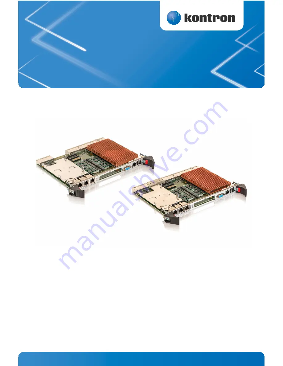
Page 11: ...l 1600 MHz DDR3L ECC memory via two SODIMM sockets providing up to 25 GB sec data throughput Thanks to hot swap support and IPMI PICMG 2 9 compliant Intelligent Platform Manage ment Interface the CPU...
Page 12: ...8 XMC Interface 1 2 3 CP6005 X SA MK2 5SATA Assembly Kit The CP6005 X SA comes with an optional CP6005 X SA MK2 5SATA assembly kit comprised of one MMADP SATA01 module and the necessary components nee...
Page 13: ...Intel QM87 PCH DMI SMB SPI PCIe FDI XDP FDI x2 PCI 64 bit DP to HDMI DVI 2x HDMI DVI 2xDDI USB 2 0 SATA Cable Conn SATA HDA HDA DDR3L w ECC SODIMM memory Channel B PCIe to PCI Mag 1000BT RJ 45 PMC XM...
Page 14: ...of the IPMI controller System Status LEDs HS blue Hot Swap Status TH red green Temperature Status WD green Watchdog Status General Purpose LEDs LED3 0 red green amber General Purpose POST Code Note If...
Page 15: ...Figure 3 4 HP CP6005 SA Board Layout Top View 4th Gen Intel Core i7 i5 Battery J12 GbE E J11 GbE B J10 GbE A J14 J16 J15 IPMI WD TH LEDs GP POST CODE LEDs J17 J18 J19 J5 J3 J2 J1 J13 J6 HS LED J7 J8...
Page 16: ...rd Layout Top View 4th Gen Intel Core i7 i5 Battery J12 GbE E J11 GbE B J10 GbE A J14 J16 J15 IPMI WD TH LEDs GP POST CODE LEDs J17 J18 J19 J5 J41 J4 J3 J2 J1 J13 J6 HS LED J7 J8 J9 J20 J21 Intel QM87...
Page 17: ...D R A F T F O R I N T E R N A L U S E O N L Y 17 www kontron com User Guide CP6005 X SA Figure 5 4 HP CP6005 X SA Board Layout Bottom View ON 4 3 2 1 4 3 2 1 ON SW2 J25 SW1...
Page 18: ...ystem controller operation 64 bit 66 MHz PCI or PCI X master interface with dedicated PCIe to PCI X bridge 3 3V or 5V signaling levels universal signaling support Compliant with the Packet Switching S...
Page 19: ...ort Gigabit Ethernet controller Three RJ 45 connectors on the front panel Two ports on the rear I O PICMG 2 16 USB Six USB ports supporting UHCI USB 1 1 and EHCI USB 2 0 Two type A USB 2 0 connectors...
Page 20: ...switch for hot swap purposes integrated in the front panel in accordance with PICMG 2 1 Rev 2 0 Timer Real Time Clock Real time clock with 256 Byte CMOS RAM battery backup available Watchdog Timer Sof...
Page 21: ...legacy BIOS compatibility based on Phoenix SCT3 Command shell for diagnostics and configuration uEFI Shell commands executable from mass storage device in a pre OS envi ronment open interface IPMI Fir...
Page 22: ...ational load 20 C to 70 C typical refer to the battery manufacturer s specifications for exact range Storage no load 40 C to 70 C typical Climatic Humidity 93 RH at 40 C non condensing acc to IEC 6006...
Page 23: ...2 EN61000 6 3 Immission EN55024 EN61000 6 2 Electrical Safety EN60950 1 Mechanical Mechanical Dimensions IEEE 1101 10 Environmental Climatic Humidity IEC60068 2 78 see note below WEEE Directive 2002 9...
Page 24: ...Backplane Specification PICMG 2 9 Rev 1 0 CompactPCI System Management Specification PICMG 2 1 Rev 2 0 CompactPCI Hot Swap Specification IPMI Intelligent Platform Management Interface Specification v...
Page 25: ...processors for use with the CP6005 X SA please contact Kontron Table 5 Features of the Processors Supported on the CP6005 X SA FEATURE Intel Core i7 4860EQ SV 1 8 GHz Intel Core i7 4700EQ SV 2 4 GHz...
Page 26: ...be either 4 GB 8 GB or 16 GB However when the in ternal processor graphics controller is enabled the amount of memory available to applications is less than the total physical memory in the system Th...
Page 27: ...ed in the SPI boot flashes Changes made to the uEFI BIOS settings are available only in the currently selected SPI boot flash Thus switch ing over to the other SPI boot flash may result in operation w...
Page 28: ...ED flashes red at regular intervals it indicates that the processor junction tem perature has reached a level beyond which permanent silicon damage may occur and the processor has been shut off To tur...
Page 29: ...Kontron for further assistance Table 7 IPMI and HS LEDs Functions LED COLOR STATE FUNCTION I0 right red Off IPMI controller running On IPMI controller out of service or in reset state Blinking IPMI co...
Page 30: ...active amber LED1 red Hardware reset green uEFI BIOS POST bit 1 and bit 5 amber LED0 red uEFI BIOS boot failure green uEFI BIOS POST bit 0 and bit 4 amber Table 9 General Purpose LEDs Functions on the...
Page 31: ...up during boot up and the CP6005 X SA does not boot please contact Kontron for further assistance 2 7 2 USB Interfaces The CP6005 X SA provides six USB 2 0 ports Two on front I O Four on the CompactPC...
Page 32: ...rovides five 10Base T 100Base TX 1000Base T Ethernet interfaces They are based on one Intel I350 quad port Gigabit Ethernet controller and one Intel I210 IT Gigabit Ether net controller The Intel I350...
Page 33: ...ne SATA 6 Gb s port on the standard SATA connector J14 for connection to SATA devices via cable Four SATA 3 Gb s ports on the CompactPCI rear I O interface All six SATA interfaces provide high perform...
Page 34: ...ated so that it cannot communicate with the CompactPCI bus This mode is known as passive mode 2 7 9 2 Board Functionality when Installed in System Slot In the system slot the CompactPCI interface can...
Page 35: ...atures are required Power ramping Precharge Hot swap control and status register bits Automatic interrupt generation whenever a board is about to be removed or replaced A Hot Swap LED to indicate that...
Page 36: ...is designed for a CompactPCI bus architec ture The CompactPCI standard is electrically identical to the PCI local bus However these systems are enhanced to operate in rugged industrial environments a...
Page 37: ...D 9 AD 8 M66EN C BE 0 GND 20 NC AD 12 GND V I O AD 11 AD 10 GND 19 NC 3 3V AD 15 AD 14 GND AD 13 GND 18 NC SERR GND 3 3V PAR C BE 1 GND 17 NC 3 3V IPMB SCL IPMB SDA GND PERR GND 16 NC DEVSEL PCIXCAP V...
Page 38: ...Table 18 CompactPCI Bus Connector J1 Peripheral Slot Pinout PIN Z A B C D E F 25 NC 5V 3 3V 5V GND 24 NC 5V V I O GND 23 NC 3 3V 5V GND 22 NC GND 3 3V GND 21 NC 3 3V GND 20 NC GND V I O GND 19 NC 3 3V...
Page 39: ...6 NC RSV RSV DEG GND RSV GND 15 NC RSV GND FAL REQ5 GNT5 GND 14 NC AD 35 AD 34 AD 33 GND AD 32 GND 13 NC AD 38 GND V I O AD 37 AD 36 GND 12 NC AD 42 AD 41 AD 40 GND AD 39 GND 11 NC AD 45 GND V I O AD...
Page 40: ...n the rack as there is practically no cabling on the CPU board For the system rear I O feature a special backplane is necessary The CP6005 X SA with rear I O is compatible with all standard 6U Compact...
Page 41: ...DB LPa_DB GND LPa_DD LPa_DD GND 16 NC LPb_DA LPb_DA GND LPb_DC LPb_DC GND 15 NC LPb_DB LPb_DB GND LPb_DD LPb_DD GND 14 NC LPa LINK LPb LINK LPab CT1 RSV FAN SENSE2 GND 13 NC LPa ACT LPb ACT RSV RSV FA...
Page 42: ...1 NC RSV HDMI1 HPDET GND HDMI1 SDA HDMI1 SDC GND 10 NC HDMI1 CLK HDMI1 CLK GND RSV RSV GND 9 NC GND GND GND GND GND GND 8 NC SATA3 TX SATA3 TX GND SATA3 RX SATA3 RX GND 7 NC GND GND GND GND GND GND 6...
Page 43: ...liant with the PICMG 2 20 specification Table 25 High Speed Serial Rear I O Connector J41 Pinout POS A B C D SIGNAL DRIVEN BY SIGNAL DRIVEN BY SIGNAL DRIVEN BY SIGNAL DRIVEN BY 1 PE1_RST Board Tristat...
Page 44: ...KPL PE1_RX1 BCKPL 19 PE1_TX0 Board PE1_TX0 Board PE1_RX0 BCKPL PE1_RX0 BCKPL 20 PE1_CLK Board Tristate PE1_CLK Board Tristate NC PE2_CLK NC PE2_CLK Table 27 High Speed Serial Rear I O Connectors J41 a...
Page 45: ...upporting 10GBASE KR 40GBASE KR4 one x8 PCI Express 3 0 port operating at 8 GT s and two SATA 6 Gb s ports Note The PICMG 2 20 configuration allows coexistence with PICMG 2 16 fabrics Table 28 High Sp...
Page 46: ...SWITCH SETTING FUNCTIONALITY 1 OFF Boot up with POST code indication on LED3 0 ON Boot up with no POST code indication on LED3 0 2 OFF Boot from the standard SPI boot flash ON Boot from the recovery...
Page 47: ...DL 0x290 LED Configuration Register LCFG 0x291 LED Control Register LCTRL 0x292 General Purpose Output Register GPOUT 0x293 General Purpose Input Register GPIN Table 32 Write Protection Register WPROT...
Page 48: ...t status 0 Reset is logged by the IPMI controller 1 Reset is not logged by IPMI controller The uEFI BIOS software sets this bit to inform the IPMI controller that the next reset should not be logged 3...
Page 49: ...MB address to the CP6005 X SA Note The Geographic Addressing Register is set to default values by power on cold reset not by a warm reset Table 34 Board ID High Byte Register BIDH ADDRESS 0x288 BIT 7...
Page 50: ...t mode 11 Cascaded mode dual stage mode 4 WEN WTR Watchdog enable Watchdog trigger control bit 0 Watchdog timer not enabled Prior to the Watchdog being enabled this bit is known as WEN After the Watch...
Page 51: ...sed For further information on read ing the 8 bit uEFI BIOS POST Code refer to Chapter 2 7 1 3 General Purpose LEDs Table 37 Board ID Low Byte Register BIDL ADDRESS 0x28D BIT 7 6 5 4 3 2 1 0 NAME BIDL...
Page 52: ...LEDs indicated in the LED Configuration Register see Table 38 are configured in General Purpose Mode Table 39 LED Control Register LCTRL ADDRESS 0x291 BIT 7 6 5 4 3 2 1 0 NAME LCMD LCOL ACCESS R W R W...
Page 53: ...urpose input signals of the rear I O CompactPCI connectors Table 40 General Purpose Output Register GPOUT ADDRESS 0x292 BIT 7 6 5 4 3 2 1 0 NAME Reserved GPO3 GPO2 GPO1 GPO0 ACCESS R R W R W R W R W R...
Page 54: ...order to be used with the CP6005 X SA Beginning at 10 of the nominal output voltage the voltage must rise within 0 1 ms to 20 ms to the specified regulation range of the voltage Typically 5 ms to 15 m...
Page 55: ...must be switched off for at least 10 sec onds before it may be switched on again If problems still occur turn off the main power for 30 seconds before turning it on again 4 2 Power Consumption The go...
Page 56: ...o Boost Technology was disabled These values represent the power dissipation reached under realistic OS controlled applica tions with the processor operating at maximum performance Work load Maximum T...
Page 57: ...GT2 Core i5 4400E SV 2 7 GHz GT2 12 V 0 1 W 0 1 W 0 1 W 0 1 W 5 V 6 0 W 6 0 W 6 0 W 6 0 W 3 3 V 7 0 W 7 0 W 7 0 W 7 0 W Total 13 1 W 13 1 W 13 1 W 13 1 W Table 45 Workload Typical NOMINAL VOLTAGE Core...
Page 58: ...ard P1386 Draft 2 4a The maximum power of 7 5 W can be arbitrarily divided on the 3 3 V and 5 V voltage lines The following table indicates the current of a PMC module Table 47 Power Consumption of CP...
Page 59: ...her 5 V or 12 V in the ANSI VITA 42 0 200x XMC Switched Mezzanine Card Auxiliary Standard specification On the CP6005 X SA the VPWR is configured to 5 V The following table indicates the current of an...
Page 60: ...the available airflow will differ The maximum ambient operating temperature must be deter mined for such environments How to read the diagram Select a specific CPU and choose a specific working point...
Page 61: ...ith Core i7 4860EQ SV 1 8 GHz Figure 9 CP6005 X SA with Core i7 4700EQ SV 2 4 GHz Maximum Volumetric Flow Rate CFM Volumetric Flow Rate m3 h recommended operating range Minimum Airflow m s Max Airflow...
Page 62: ...GHz Figure 11 CP6005 X SA with Core i5 4400E SV 2 7 GHz Typical Maximum Volumetric Flow Rate CFM Volumetric Flow Rate m3 h recommended operating range Minimum Airflow m s Max Airflow Input Temp C Typ...
Page 63: ...en for the application It may very well be necessary to revise system requirements to comply with operational environment conditions In most cases this will lead to a re duction in the maximum allowab...
Page 64: ...6005 X SA 6 2 Technical Specifications 6 3 MMADP SATA01 Module Layout The MMADP SATA01 module includes one board to board connector J1 for connection to the CP6005 X SA board and one standard SATA con...
Page 65: ...Note Write protection is available for this module Contact Kontron for further assistance if write protection is required 7 2 SATA Flash Module Layout Figure 13 SATA Flash Module Layout Bottom View Ta...
Page 66: ...duct with his her hands or tools This is most easily done by touching a metal part of your system housing Do not handle this product out of its protective enclosure while it is not used for operationa...
Page 67: ...ngage the board with the backplane When the ejector handles are closed the board is engaged 4 The blue HS LED turns on and then off indicating that the CP6005 X SA is operating 5 Fasten the front pane...
Page 68: ...and the MMADP SATA01 module which is required for connecting an onboard HDD SSD to the CP6005X SA Prior to installation of a peripheral device ensure that the safety requirements are met Special atten...
Page 69: ...evice fail message at boot up may be a bad cable or lack of power going to the drive 8 4 3 Onboard 2 5 HDD SSD Installation One 2 5 SATA HDD SSD may be directly connected to the board via the adapter...
Page 70: ...cted a request for password will appear Enter either the User Password or the Supervisor Password see Security menu press RE TURN and proceed with step 5 5 A Setup menu will appear The CP6005 X SA uEF...
Page 71: ...displayed This screen lists the Main Setup menu sub screens and provides basic system information as well as functions for setting the system time and date Table 55 Main Setup Menu Sub Screens and Fu...
Page 72: ...6005 X SA for possible LFM HFM values The active nominal CPU frequency is Ratio 100MHz ME Configuration ME FW Downgrade Enables Disables ME FW Downgrade function Table 57 Security Setup Menu Functions...
Page 73: ...ndling changes made to the uEFI BIOS settings and the exiting of the Setup program Table 59 Boot Priority Order FUNCTION DESCRIPTION Boot Priority Order 1 Internal Shell Keys used to view or configure...
Page 74: ...s the first boot option by default 9 3 1 1 Entering the uEFI Shell To enter the uEFI Shell follow the steps below 1 Power on the board 2 Ignore the message Press the F2 key 3 Press the ESC key within...
Page 75: ...ges are stored Note The parameters of the kBoardConfig command are not case sensitive kBoardInfo Shows a summary of board specific data and displays checks various parameters such as the current uEFI...
Page 76: ...sword Controls uEFI Setup and Shell passwords This command is used to determine the status of both passwords set or not set and to set or clear the uEFI Shell and Setup passwords Both user and superus...
Page 77: ...ent variable used to control the execution flow The following sam ple start up script shows the uEFI Shell environment variable wdt_enable used to control the Watchdog To create a uEFI Shell environme...
Page 78: ...he images are automatically detected during boot up and an update of the uEFI BIOS or the IPMI firmware is carried out 9 5 1 Updating the uEFI BIOS 9 5 1 1 uEFI BIOS Fail Over Mechanism The CP6005 X S...
Page 79: ...05 X SA s IPMI controller has an internal flash where the boot block or the active IPMI firm ware is running from as well as an external flash where two IPMI firmware images are stored namely a copy o...
Page 80: ...the CP6005 X SA s IPMI firmware Keyboard Controller Style KCS interface Dual port IPMB interface for out of band management and sensor monitoring IPMI over LAN IOL and Serial over LAN SOL support Sens...
Page 81: ...the IPMI Device Information Record included in the SMBIOS table 10 3 Supported IPMI and ATCA Commands 10 3 1 Standard IPMI Commands The following table shows an excerpt from the command list specified...
Page 82: ...pp 55h O Yes Set Channel Security Keys 22 25 App 56h O No Get System Interface Capabilities 22 9 App 57h O No CHASSIS DEVICE COMMANDS O Get Chassis Capabilities 28 1 Chassis 00h O Yes Get Chassis Stat...
Page 83: ...s Get SDR 33 12 Storage 23h O Yes Add SDR 33 13 Storage 24h O Yes Partial Add SDR 33 14 Storage 25h O Yes Delete SDR 33 15 Storage 26h O Yes Clear SDR Repository 33 16 Storage 27h O Yes Get SDR Reposi...
Page 84: ...LAN Configuration Parameters 23 2 Transport 02h O Yes Suspend BMC ARPs 23 3 Transport 03h O No Get IP UDP RMCP Statistics 23 4 Transport 04h O Yes SERIAL MODEM DEVICE COMMANDS 25 1 to 25 12 Transport...
Page 85: ...ID Command COMMAND LUN NetFn CMD Get Device ID 00h App 06h 01h REQUEST DATA Byte Data Field RESPONSE DATA Byte Data Field 1 Completion code 2 10h Device ID 3 80h Device Revision 4 02h Firmware Revisi...
Page 86: ...t up the uEFI BIOS reports its operational status to the IPMI controller within a given time If the status is failed or not reported within the given time the IPMI controller selects the recovery SPI...
Page 87: ...oot flash selection 9Dh uEFI BIOS boot order configuration 2 Control state for SPI boot flash selection 00h 00h Standard SPI boot flash is selected default 01h Recovery SPI boot flash is selected Note...
Page 88: ...ngs Table 66 Get Control State COMMAND LUN NetFn CMD Get Control State SPI Boot Flash Boot Order 00h OEM 3Eh 21h REQUEST DATA Byte Data Field 1 Control ID 00h SPI boot flash selection 9Dh uEFI BIOS bo...
Page 89: ...ix will be Sxx where xx is the slot number e g 09 The sensor number is the number which identifies the sensor e g when using the IPMI command Get Sensor Reading Please note that ipmitool accepts senso...
Page 90: ...EL and in system slot SYSEN N 11h NNN IPMI WD Watchdog2 23h Sensor specific 6Fh 010Fh 0000h 010Fh IPMI watchdog Y 010Fh 12h NNN IPMB State IPMB status change F1h Sensor specific 6Fh 000Fh 0000h 000Fh...
Page 91: ...Firmware Info 2 C0h OEM 71h 0003h 0000h 7FFFh For internal use only N 22h NNN IniAgent Err Initialization Agent C2h digital Discrete 03h 0002h 0000h 0003h Initialization agent error sta tus Used on BM...
Page 92: ...l min 3 C 3 C 0 C 0 C Lower non critical 1 C n a 1 C 40 C Lower critical n a n a 2 C 42 C Lower non recoverable n a n a 5 C 45 C Table 69 Voltage Sensor Thresholds Sensor Number ID String 06h NNN Boar...
Page 93: ...Error is detected if the POST code is 0 and doesn t change for a defined amount of time In case of no error Bits 7 0 POST code payload Port 80h In case of error Bits 15 0 4000h Data2 POST code low nib...
Page 94: ...payload is off even if the IPMI firmware re boots To disable the write protection mode plug the board in a non write protected Com pactPCI slot and switch on the payload 10 10 LAN Functions Four Gigab...
Page 95: ...1 85386 Eching Munich Germany Tel 49 0 8165 77 777 Fax 49 0 8165 77 219 info kontron com North America 14118 Stowe Drive Poway CA 92064 7147 USA Tel 1 888 294 4558 Fax 1 858 677 0898 info us kontron...