Introduction
CP-RIO6-001/-DD-216/-HD/-HD-216
Page 1 - 10
ID 1043-5620, Rev. 2.0
1.4
Technical Specification
Table 1-2: CP-RIO6-001/-DD-216/-HD/-HD-216 Main Specifications
CP-RIO6-001/-DD-216/
-HD/-HD-216
SPECIFICATIONS
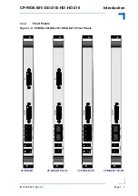
Front Panel I
nterfaces
Digital Video
CP-RIO6-001, CP-RIO6-001-DD-216:
•
Two digital video interfaces implemented as two 29-pin DVI-I con-
nectors, J9 and J11, supporting HDMI and DVI signaling for digital
monitors (no analog video signals on these connectors)
CP-RIO6-001-HD, CP-RIO6-001-HD-216:
•
One digital video interface implemented as a 29-pin DVI-I connector,
J9, for connecting a monitor with a DVI/HDMI interface (no analog
video signals on this connector)
Ethernet
CP-RIO6-001, CP-RIO6-001-HD:
•
Two Gigabit Ethernet interfaces implemented as a dual RJ-45 con-
nector, J8A/B
CP-RIO6-001-DD-216, CP-RIO6-001-HD-216:
•
Ethernet not supported due to the fact that the Ethernet interface is
isolated on the CompactPCI connector rJ3
USB
Two USB 2.0 interfaces on type A connectors, J6 and J7
Onboard Interfaces
SATA
CP-RIO6-001, CP-RIO6-001-DD-216:
•
One SATA interface implemented as one onboard connector, J17,
for connecting a SATA device via a SATA cable
CP-RIO6-001-HD, CP-RIO6-001-HD-216:
Two SATA interfaces implemented as two onboard connectors:
•
One SATA connector, J17, for connecting a SATA device via a
SATA cable
•
One SATA connector, J19, for installing a 2.5” SATA HDD/SSD
(optional)
USB
One onboard connector, J18, for connecting one USB 2.0 NAND Flash
module
COM
Two onboard COM ports implemented as two 10-pin, 2.54 mm onboard
connectors, J15 and J16
Fan
Two fan connectors, J12 and J13, with PWM control and sense inputs for
monitoring the fan speed.
CompactPCI
Three CompactPCI connectors, rJ3, rJ4 and rJ5, for connecting the
module to the backplane


