Konica Minolta bizhub C754 Installation Manual Download Page 2

E-2

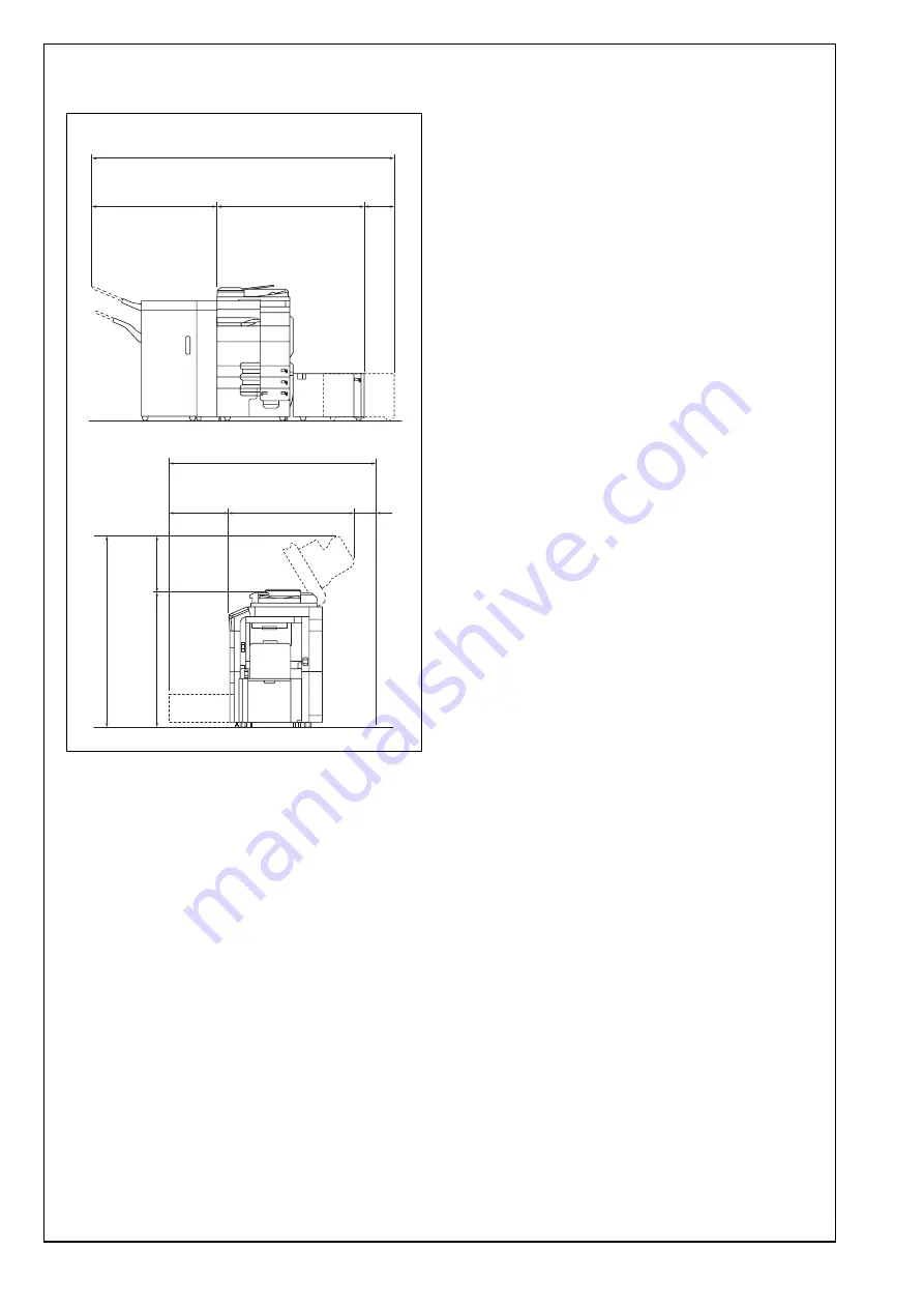
II. Installation space (unit: mm (inch))

bizhub C754 + ZU-606 + FS-535 + LU-204

III. Pre-installation check items

1. Select a level and stable place for installing the 

machine.

2. Be sure to use a power source of the voltage and 

frequency indicated in the product specifications. 
Ensure that the current carrying capacity of the 
power outlet is at least equal to the current listed 
in the product specifications.

3. Power the machine directly from a dedicated 

power outlet. (Do not use an extension cord.)

4. Do not plug or unplug the power cord with wet or 

dirty hands, otherwise you may get an electric 
shock.

5. Avoid a hot and humid environment, or a place 

exposed to direct sunlight.

6. Avoid a dusty location, or a place near volatile 

and flammable substances.

7. Avoid a poorly ventilated place.

IV. Notes on using touch panel

Be sure to instruct users on the following points.
    • This machine uses a capacitive touch panel. 

When you touch the touch panel, use your fin-
ger or the stylus pen supplied with the machine. 
If you touch the panel using your nail or a pen 
tip instead of using your finger or the stylus pen, 
the touch panel does not respond normally. 

    • Pressing the touch panel hard may cause dam-

age.

    • Do not strongly press the panel or press it using 

the sharp tip of mechanical pencils.

    • The key is a finger tapping (quick light touch 

using a finger) operation.

A2X0IXC002DA

498

(19-5/8)

1027

(40-7/16)

11

55

(45-

1/2

)

495

(1

9-

1/2)

1252

(49-5/16)

1575 (62-1/16)

16

50 (

64

-1

5/1

6)

238

(9-3/8)

50

(2)

1066

(41-15/16)

2556 (100-5/8)

Summary of Contents for bizhub C754

Page 1: ...itch is turned ON do not turn OFF it until the installation work has been completed When transporting the machine assign an ade quate number of persons to the job and follow the specified correct proc...

Page 2: ...xposed to direct sunlight 6 Avoid a dusty location or a place near volatile and flammable substances 7 Avoid a poorly ventilated place IV Notes on using touch panel Be sure to instruct users on the fo...

Page 3: ...cushion A that are removed in this step for later use The cushion B contains accessory parts Depending on the applicable marketing area the cushion B may also contain the power cord 2 Remove the fixin...

Page 4: ...lustrated and drive nails in to fix the slope in position Caution Insert the nails in the outer holes 7 Holding onto the front cover and the back panel of the machine slide the machine down along the...

Page 5: ...erials upper 3 Hold onto the handle of the machine and tilt the machine to the right and left Under this condition remove the fixing materials lower 4 Place the jig slope as shown and insert the nails...

Page 6: ...equate number of persons When sliding the machine down do not hold onto the scanner portion Do not insert your leg under the slope VII Removing protective tape packing and other shipping materials 1 R...

Page 7: ...tive sheet from the control panel 5 Pull the tray 1 out and remove the protective tape from the tray 6 Pull the tray 2 out and remove the protective tape from the tray 7 Pull trays 3 and 4 out and rem...

Page 8: ...ling the toner cartridges Note Since no toner cartridges are supplied with the machine purchase a toner cartridge of different colors separately 1 Open the upper front door 2 Shake the toner cartridge...

Page 9: ...e is pushed all the way in 6 Using the same procedure install the toner car tridges for other colors of toner 7 Close the upper front door IX Mounting the accessory parts 1 Attach the supplied caps A...

Page 10: ...sheet is affixed on customer request The panel sheet must be kept by the customer XI Installing the user s guide holder Install the user s guide holder XII Installing the set guide for banner paper Op...

Page 11: ...when necessary upon your customer s request 1 Raise the operation panel 2 Slide the touch panel 3 Remove the small cover from the back of the operation panel 4 Install and tighten the screw as shown...

Page 12: ...or Letter paper 2 Display the Service Mode screen For details of how to display the Service Mode screen see the service manual 3 Touch Imaging Process Adjustment 4 Touch Gradation Adjust 5 Check that...

Page 13: ...the machine read the test pattern two times 18 Touch END If A4 or Letter paper is set in step 1 6 Touch Print select A4 8 11 and press the start key A test pattern will then be produced on the two A4...

Page 14: ...pattern the Gradation Adjust screen will reap pear 17 Repeat steps from 12 through 15 to let the machine read the test pattern two times 18 Touch END XVIII Adjusting the height 1 Check the clearance...

Page 15: ...ting leading edge skew front side Note Perform this adjustment if necessary 1 Close the reverse automatic document feeder 2 Check how the edges of the chart are misaligned The amount of the deviation...

Page 16: ...crew be sure not to raise the reverse automatic document feeder until in an upright position To prevent the adjustment screw breakage be sure to follow the above instructions 9 When the difference of...

Page 17: ...ence between the deviation of the chart and the deviation of the sample Difference of the deviation Z X Specifications 0 2 0 mm If the difference of the deviation does not fall within the specified ra...

Page 18: ...ake full size copies 3 Check whether the difference in the width C between the chart and the copy sample is within the specified range Difference in the width C C of the copy sample C of the chart Spe...

Page 19: ...llowing adjustment 16 Display the Service Mode screen For details of how to display the Service Mode screen see the service manual 17 Touch ADF 18 Touch FD Mag Adj B 19 Check that Orig Feed Zoom Ad is...

Page 20: ...ater than the specifications use the minus key If the difference in the width D is smaller than the specifications use the plus key 33 Touch END 34 Touch Exit on the Service Mode screen 35 Turn OFF an...

Page 21: ...Display the Service Mode screen For details of how to display the Service Mode screen see the service manual 7 Touch ADF 8 Touch Original Stop Position 9 Touch Sub Scanning Direction 1 Side or Sub Sc...

Page 22: ...For details of how to display the Service Mode screen see the service manual 21 Touch ADF 22 Touch Original Stop Position 23 Touch Main Scanning Front or Main Scan ning Back 24 While looking at the co...

Page 23: ...me setting 1 Display the Service Mode screen For details of how to display the Service Mode screen see the service manual 2 Display the Date Time Setting screen To display the Date Time Setting screen...

Page 24: ...Load the tray 1 with A4 or Letter paper 2 Touch List Output 3 Check that Machine Management List is selected and press the start key The list will be output 4 Output Adjustments List in the same way 5...

Page 25: ...Display the Service Mode screen For details of how to display the Service Mode screen see the service manual 12 Select the LCC size setting function as follows System 2 LCT Build in Size Settings 13...

Page 26: ...rk con nection has been made LED2 Should blink according to the communications status of the ACT network XXXV Network setting Make the TCP IP address setting for the network Note Consult the network a...

Page 27: ...eeding tray Note Take care so that the document feed tray will not fall down during operation 5 Remove two screws shown on the illustration and remove the plate cover No Name Shape Q ty 1 Stamp unit 1...

Page 28: ...that has been removed in step 5 Two screws 12 Mount the mounting plate removed in step 3 One screw 13 Set the document feeding tray down 14 Close the left cover of the reverse automatic document feede...

Reviews: