background image

Chapter 4 Confirming Operation Using Service Tool

4-4


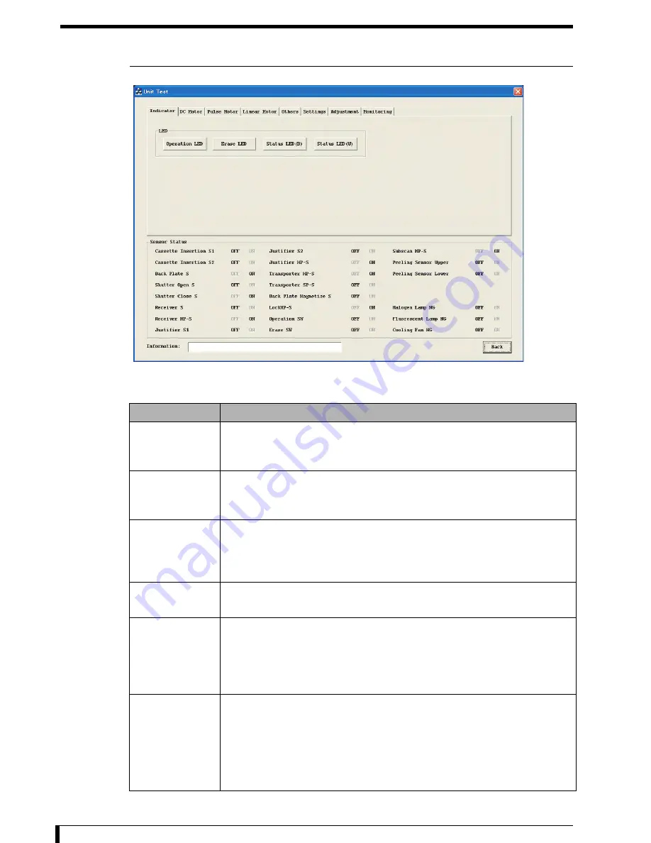
4.2.2 Function Outline of the [Unit Test] Screen

[Unit Test] is composed of 8 screens, and panels are switched using the tab.
Contents of each panels are as following:

Panel name

Description

Indicator

Stand-alone operation for following units can be confirmed.

Lamps on the operation panel

Status lamp

DC Motor

Stand-alone operation for following units can be confirmed.

Shutter Motor

Lock Motor

Pulse Motor

Stand-alone operation for following units can be confirmed.

Receive Motor

Justifier Motor

Transporter Motor

Linear Motor

Stand-alone operation for following units can be confirmed.

Subscan Motor

Others

Stand-alone operation for following units can be confirmed.

Barcode reader

Polygon Mirror

Halogen Lamp

Fluorescent Lamp

Settings

Following setups can be performed.

Display language

Speaker volume

Also, stand-alone operation for following units can be confirmed.

LCD

Speaker

Summary of Contents for 0902

Page 1: ...Service Manual DIRECT DIGITIZER CODE NO 0902 REGIUS MODEL 110 2970 Ishikawa machi Hachioji shi Tokyo 192 8505 Japan Manufacturer 0197...

Page 2: ......

Page 3: ...anual is prohibited 2 The contents of this manual are subject to change without notice 3 Any discrepancies errors or omissions noted should be communicated to the manufacturer 4 Notwithstanding item 3...

Page 4: ...es how to confirm the operation of the REGIUS MODEL 110 Chapter 5 Disassemble and Assemble This chapter describes how to disassemble and assemble the equipment Chapter 6 Adjustment This chapter descri...

Page 5: ...s is used for a direct and urgent danger that can cause death or severe injury major damage to the property like complete destruction of the equipment or fire if not avoided WARNING This is used for a...

Page 6: ......

Page 7: ...5 2 3 1 Equipment Specification 2 5 2 3 2 Read Erase of the Image 2 6 2 3 3 Control Unit Performance 2 8 2 4 Block Diagram 2 9 2 5 Position of Major Components 2 11 2 5 1 Insertion Unit 2 11 2 5 2 Rec...

Page 8: ...Error 3 32 3 3 1 Network Related 3 32 3 3 2 Power ON OFF Related 3 34 3 3 3 Signal Processing Related 3 37 3 4 How to Respond on Image Defect 3 38 3 4 1 Flow of Response 3 38 3 4 2 Image is Dark or Bl...

Page 9: ...ng Installing the Optical Unit 5 11 5 2 6 Moving the Push Plate Unit 5 17 5 2 7 Binding the Grounding Strap 5 18 5 3 Replacing the Parts on the Insertion Unit 5 19 5 3 1 Replacing the Operation Unit O...

Page 10: ...ng the Detach Detection Roller 5 89 5 9 Replacing the Parts on the Exterior 5 90 5 9 1 Replacing the Second Front Door Lock Mechanisms 5 90 5 9 2 Replacing the Interlock Switch 5 93 5 9 3 Replacing th...

Page 11: ...11 7 2 8 Greasing Transporter Lead Screw Unit and Transporter Motor Unit Assembly Gear Mechanism Unit 7 12 7 2 9 Greasing of Release Shaft Holder 7 13 7 2 10 Greasing Justifier Motor Unit Assembly Gea...

Page 12: ......

Page 13: ...Chapter 1 Chapter 1 Safety Warnings and Cautions The caution regarding the safety before performing the repair maintenance is described here 1 1 Warning Labels 1 2 1 2 Safety Caution 1 5...

Page 14: ...arning cables during the installation or repair maintenance is performed 1 1 1 Position and Type of Warning Label Exterior and optic unit Position will differ depending on the operation panel position...

Page 15: ...rnings and Cautions 1 3 No Contents Warning label No Contents Warning label 1 Class 1 laser product 2 Laser caution 3 Do not sit 4 Laser output 5 Clearing a jam and lamp replacement procedures 6 High...

Page 16: ...Chapter 1 Safety Warnings and Cautions 1 4 7 Interlock Caution 8 Magnetism Warning 9 Magnet No Contents Warning label No Contents Warning label...

Page 17: ...s stored or where the gas is generated 5 Note the frequency and allowable current or power consumption of the power supply 6 Confirm the status abandoned status polarity etc of the battery power suppl...

Page 18: ...ely when operation is resumed after it has not been used for an extended period 10 Operate properly in accordance with the User Manual 1 2 2 General Caution Do not perform any operation that is not me...

Page 19: ...t Do not block the air intake or outlet of the equipment It is possible that equipment to break or decrease the image read quality when the air intake and outlet of the equipment is blocked Do not pla...

Page 20: ...nstalled on the CIU PCB in the equipment There is a risk of explosion when the lithium battery is placed near the fire or place in the water Use the wrist band when handling the electronic parts insid...

Page 21: ...rming the repair maintenance are described 2 1 Name of Parts 2 2 2 2 Structure 2 4 2 3 Principal Specifications 2 5 2 4 Block Diagram 2 9 2 5 Position of Major Components 2 11 2 6 Operation 2 20 2 7 H...

Page 22: ...lights flashing alternately Malfunction 4 Dummy operation panel A cover on the side where the operation panel is not connected out of 2 operation panel attachment locations 5 Operation panel Message d...

Page 23: ...3 6 No Name Function 1 Message display window Displays the status and errors of the REGIUS MODEL 110 2 operation lamp Turns on when operation switch is turned ON Off Stopped Green light on Starting u...

Page 24: ...he cassette locked in the receiver unit will be moved to reading position first front back side 5 Receiver unit Take in the cassette into the equipment with the receiver mechanism and fix the cassette...

Page 25: ...midity During operation 15 30 C 35 80 RH no condensation Not operating 10 40 C 10 95 RH no condensation Periodic replacement parts Erase lamp unit erase count About 30 000 shots Accessories Power supp...

Page 26: ...251 500 QR value definition Define as QR 200 when the output signal value in 12 bit output is 1535 steps with 2 58 x 10 7 C kg 1 mR is exposed with 80 kV tube voltage Reading dynamic range Normal D r...

Page 27: ...meter 100 m or less main and sub Lens 2 group 2 lens Method Light condensing by light guide and light condensing mirror Elimination of exciting light Elimination with exciting light cut filter Method...

Page 28: ...eive various commands A function to send the read image data to the specified destination A function to notify the equipment status Control functions A function to perform sequence of controls such as...

Page 29: ...S15 Detach Detection Sensor Bottom S16 Halogen Lamp HL1 Hot Cathode Tube Lamp Receiver Sensor S6 Receiver HP Sensor S7 Receiver Motor PM2 Mechanical Linkage Mechanical Linkage Mechanical Linkage Trans...

Page 30: ...2 10...

Page 31: ...the cassette It is OFF when there is no back plate 5 3 6 Replacing the Back Plate Drop Detection Sensor Page 5 27 5 Eraser cooling fan Intakes air to cool the eraser unit 5 3 3 Replacing the Eraser C...

Page 32: ...he Justifier Motor Page 5 44 5 Justifier standard sensor Detects the presence of cassette when it is fixing the cassette It goes ON when there is a cassette 5 4 4 Replacing the Justifier Standard Sens...

Page 33: ...es ON when the push plate is at the read position 3 5 10 5 Replacing the Transporter Read Sensor Page 5 126 3 Transporter HP sensor 1 It goes ON when the push plate unit is at the home position 5 10 4...

Page 34: ...5 72 3 Magnet shaft A shaft for the subscan motor Cannot replace on site 4 LM block A block running on top of the LM guide Use these grease nipples to grease Cannot replace on site 5 Subscan motor LM...

Page 35: ...Halogen Lamp Page 5 88 2 Hot cathode tube lamp Erase the recording of the plate 5 7 2 Replacing the Hot Cathode Tube Lamp Page 5 87 No Name Function Reference on replacement method 3 Inverter An inve...

Page 36: ...t from the push plate unit it will touch the detach detection roller during the read This movement will be detected by the detach sensor sensor goes ON and determined as an error 5 8 3 Replacing the D...

Page 37: ...12 Replacing the Transformer Page 5 113 4 Digital power supply Supplies the power supply 5 V 24 V for the digital components of the LMC CIU and MDU 5 9 11 Replacing the Digital Power Supply Page 5 11...

Page 38: ...it Relay Interlock Relay 2 Page 5 106 10 Standby power supply A power supply that is constantly ON 5 9 9 Replacing the Standby Power Supply Page 5 108 11 Halogen power supply Supply the power supply t...

Page 39: ...5 119 4 Tumbler top A circuit board to fix the push plate unit to read position with a spring 5 10 9 Replacing the Tumbler Upper Page 5 133 5 Transporter motor Move the push plate unit 5 10 6 Replaci...

Page 40: ...e image See Routine Mode Operation Transition Diagram Page 2 21 for more description about the status transition Sleep mode A sleep status engaged with turning OFF the REGIUS console Maintenance mode...

Page 41: ...out Image Erase Action Fast Erase Initialization Process Press erase Switch for 3 Seconds Press operation Switch Press operation Switch for 3 Seconds ERASE MODE QUICK Status Countdown Press operation...

Page 42: ...r reads the barcode Following check will be performed by barcode reader reading the barcode If the barcode is correctly read If the plate size is smaller than calibration size If there is no discrepan...

Page 43: ...ting the receiver motor for appropriate pulses depends on the cassette size after the justifier guide completes its move Second falling position Position of the lock lock release mechanism and open cl...

Page 44: ...urn on the laser and read the image from the plate If there is a warp or detach of the plate this will contact the detach detection roller then detected by detach detection sensor and an error is gene...

Page 45: ...late 67 Push plate unit will move to the home position Shutter will also open Transporter motor will rotate in reverse direction to move the push plate unit to the home position Shutter will also open...

Page 46: ...sertion slot will detect ejection of the cassette Ejecting of cassette is completed when the following sensors turns OFF Insert slot detection sensor 1 Insert slot detection sensor 2 Back plate drop d...

Page 47: ...n Perform warm up action and operation check of all units Warm up action Operate in a maximum operable range Initialization timing Initialization action After power on Initialization of the FPGA Initi...

Page 48: ...ely Move Receiver to HP Move Receiver to HP Receiver at HP Position Justifier at HP Position Move Justifier to HP Move Transporter to HP Move Transporter to Press Down Position Move Transporter to Rea...

Page 49: ...chanical unit Check Cassette Detection Sensor Shutter Open End Shutter Close MoveJustifierMinutelyToward CassetteFixingDirection Move Justifier to Justifier HP Transporter at Read Position Shutter Clo...

Page 50: ...aning reading unit It will go into the optical unit maintenance mode by pressing the operation switch and the erase switch simultaneously for more than 3 seconds when the equipment is in READY status...

Page 51: ...rt when the cassette is placed vertically for long period or in high temperature Always tore the opened plate in the cassette Do not store with back plate and front plate separated Especially the back...

Page 52: ...y Interlock release key Laser protection glasses Compatible to laser light of 660 nm wavelength Acoustic wave tension meter Manufacturer Gates Unitta Asia Product name Sonic Belt Tension Meter Model U...

Page 53: ...Repair 2 33 Supplied Products Jigs tools Note Alcohol Used to clean the cassette absorption plate Grease for LM guide AFC grease by THK Grease all parts except LM guide Plusguard No 2 by Kyodo Yushi W...

Page 54: ......

Page 55: ...g How to respond to a trouble on the equipment is described here 3 1 Workflow 3 2 3 2 Description of the Error Codes and How to Respond 3 5 3 3 Response to the Problems Not Displaying Error 3 32 3 4 H...

Page 56: ...mmunicate to the contact person Trouble that does not display an error message on the message display window See 3 3 Response to the Problems Not Displaying Error Page 3 32 and perform the response Ej...

Page 57: ...push plate unit is not at the read position due to operational error in the transporter eject the cassette by Step 6 3 Close the second front door Initialization will be performed Initialization will...

Page 58: ...panel 2 Move the push plate to the read position by rotating A in the image drive shaft holder 3 Eject the cassette See the instruction manual on how to eject the cassette 4 See Installation Procedur...

Page 59: ...ifier HP sensor Sensor wire JP41 MCN3 MDU Justifier motor Motor wire JJ50 MCN5 MDU MDU 06003 06018 06033 Justifier motor control error when moving to cassette fixing position There was a trouble with...

Page 60: ...tifier motor control error when moving to HP 3 There was a trouble with the motor control when the justifier guide was moving from the minute opening position to the home position Confirm following an...

Page 61: ...nsor wire JP43 MCN3 MDU Receiver motor Motor wire JP51 MCN5 MDU MDU 06053 06068 06083 Receiver motor control error when moving to first falling position There was a trouble with the motor control when...

Page 62: ...llowing and replace the faulty parts Receiver HP sensor Sensor wire JP43 MCN3 MDU Receiver motor Motor wire JP51 MCN5 MDU MDU 06060 06075 06090 Receiver motor control error when moving to HP 3 There w...

Page 63: ...r Sensor wire JP47 MCN4 MDU Transporter motor Motor wire JP52 MCN6 MDU MDU 06101 06116 06131 Transporter motor control error when moving to read position There was a trouble with the motor control whe...

Page 64: ...ion 1 Confirm the ground It may cause noise 2 Confirm that the antistatic brush right under the insertion slot has not fallen off 3 Confirm following and replace faulty parts Ground wire of transporte...

Page 65: ...oreign objects between the push plate and the frame and remove if there are any 2 Confirm if there is enough grease on the drive shaft nut or transporter motor unit and apply grease if it is not enoug...

Page 66: ...slot has not fallen off 3 Confirm following and replace the faulty parts Ground wire of transporter unit if it is not broken Transporter motor Motor wire JP52 MCN6 MDU MDU 06111 06126 06141 Transporte...

Page 67: ...uring erase operation Error codes I column Errors during initialization 06113 06128 06143 Transporter motor control error when moving to HP 2 There was a trouble with the motor control when the push p...

Page 68: ...mechanical home position 1 Confirm that the fixing shaft of the simple fixing lock is not lowered 2 Confirm there are no foreign objects on the magnet shaft of the subscan unit and remove it if there...

Page 69: ...or the procedure to replace the shutter close detection sensor See 5 3 11 Replacing the Shutter Motor Page 5 35 for the procedure to replace the ShutterMotor See 5 10 2 Replacing the MDU Page 5 116 fo...

Page 70: ...0 Lock release motor error when initializing There was a trouble with the motor control for the initialization action of the lock unit 1 Check the sliding of the release rod plunger pin and replace th...

Page 71: ...ustifier motor is appropriate and adjust it if it is out of range 3 Confirm that there is no rattling or loosening in the pulley or the gear unit of the justifier motor unit and remount the unit if th...

Page 72: ...justifier sensor See 5 10 2 Replacing the MDU Page 5 116 for the procedure to replace the MDU 06302 Cassette during the startup justifier sensor Justifier sensor or justifier standard sensor was ON d...

Page 73: ...ceiving the cassette 1 Confirm that there are no scratches or foreign objects on the cassette the receiver and the justifier guide Replace with new parts if there are any scratches or remove any forei...

Page 74: ...error Response References to replacement methods are listed at the end of the table S E I 06400 06415 06430 Back plate detection sensor error before moving to read position Back plate absorption detec...

Page 75: ...5 06480 Plate detach detection when reading or erasing Detach detection sensor went ON during the read action or the erase action Stop using the cassette with an error and request a repair at the fact...

Page 76: ...1 Sensor wire LLB2 JP32 MCN1 MDU Sensor wire LPB2 JP34 MCN1 MDU Insert slot detection sensor 2 Sensor wire LLB1 JP31 MCN1 MDU Sensor wire LPB1 JP33 MCN1 MDU Back plate drop detection sensor Sensor wi...

Page 77: ...cted after the insertion slot detection sensor went ON during the eject When the back plate is off 1 Check the cassette Are there any clicks when lock unit is pushed Is the manufacturing date of the c...

Page 78: ...Power Supply Cooling Fan Page 5 112 for the procedure to replace the digital power supply cooling fan See 5 10 2 Replacing the MDU Page 5 116 for the procedure to replace the MDU Error code Descripti...

Page 79: ...able S E I 06650 FPGA error failure on event driver access Failed on event driver access during the initialization after the PowerON 06651 FPGA error failure on access to MDU Failed to access the MDU...

Page 80: ...rocess error Offset Underflow Offset value has underflowed in the gain offset compensation process during the PowerON Wakeup 14010 Signal process error QRV Overflow PMT high voltage setup value has ex...

Page 81: ...rd data after confirming normal startup after replacing the CF card 23900 Program error Firmware update Problem in data included in the Update Kit for updating the reader firm This error is displayed...

Page 82: ...routine mode has timed out Error code Description of the error Response References to replacement methods are listed at the end of the table 26000 Operation error Invalid job There was an unsupported...

Page 83: ...s Perform the operation on the console again after the cassette is ejected 26900 Operation error PowerOFF during job execution PowerOFF was executed by pressing the operation switch right after the jo...

Page 84: ...Chapter 3 Troubleshooting 3 30 3 2 19 Confirm the H sync Signal To be stated...

Page 85: ...Chapter 3 Troubleshooting 3 31 3 2 20 Confirm the LMC Operation To be stated...

Page 86: ...t of both REGIUS console and JM is necessary When the JM is restarted without any operation after the disconnection making it able to read again Possible to read the registered image But new cassette...

Page 87: ...nger to insert the cassette after detecting the barcode only on the first read Attempt to operate from the JM that started up later will cause a registration error There are 2 REGIUS consoles with sam...

Page 88: ...sed for 3 seconds to shutdown during the READY state message display window turns off but the blinking of the LED does not stop Turn OFF the power supply circuit breaker of the equipment operation swi...

Page 89: ...asuring point MCN2 1 pin 10 pin OPB 6 Confirm that AC 110 120 V is output on the secondary connector of the transformer JJ2 and JJ3 after turning ON the power supply circuit breaker Measuring point JJ...

Page 90: ...hooting 3 36 First Front Side First Front Side Back JJ2 JP25 JJ3 Transformer JJ10 Tap Digital Power Supply Standby Power Supply Power Supply Breaker Noise Filter PCN2 Interlock Switch PCU AC Inlet MCN...

Page 91: ...menon White only compensation data image is output No Cause Response 1 There might be a 10BASE network hub or cable used in the network system Confirm the network hubs and cables No Cause Response 1 S...

Page 92: ...in the table Phenomenon not in the table Unable to respond contact Communicate the description of the condition see Information to Communicate to the contact person Investigate the cause and respond S...

Page 93: ...horizontally page 3 45 10 Top and bottom of the image is trimmed page 3 45 11 Sides of the image is trimmed page 3 45 12 Unevenness is not calibrated page 3 45 13 Unevenness calibration data is too hi...

Page 94: ...OI to the correct position No Cause Response 1 Output density in the G process parameter is set low in general See the Image Process Adjustment Manual and set the Density H L in the G process paramete...

Page 95: ...n making sure no shock is applied to the equipment No Cause 1 It could happen when there are shielding material is located at the white area No Response 1 Cause is so limited ask the user to respond b...

Page 96: ...Replacing the LMC Page 5 79 for the procedure to replace the LMC Replace the CIU See 5 10 1 Replacing the CIU Page 5 115 for the procedure to replace the CIU Important Always perform the image size a...

Page 97: ...fter replacing the optical unit No Cause Response 1 There is vertical scratch on the plate Replace the plate 2 Vignetting might be happening to the laser by the dust stuck on the tip of the condensing...

Page 98: ...he LMC Page 5 79 for the procedure to replace the LMC Replace the CIU See 5 10 1 Replacing the CIU Page 5 115 for the procedure to replace the CIU Important Always perform the image size adjustment th...

Page 99: ...out any scratch or smudge 2 Does not improve after performing the above action Replace the CF card See 5 10 3 Replacing the CF Card Page 5 118 for the procedure to replace the CF card Replace the CIU...

Page 100: ...id X ray quality tube voltage distance exposure range were identical Fluctuate compared with different model Compare with 150 S value will be different if the x ray tube grid or exposure condition are...

Page 101: ...the plate that was not erased Erase the image on the plate and redo the exposure No Cause Response 1 Density does not match the light box Regenerate the display LUT No Cause Response 1 Exposed on the...

Page 102: ...djustment the image position adjustment the unevenness calibration and the sensitivity calibration after replacing the optical unit No Cause Response 1 X ray exposure time is too long Organs will move...

Page 103: ...ds to confirm the operation of REGIUS MODEL 110 is described here 4 1 Before Confirming the Operation 4 2 4 2 Display Unit Test Screen 4 3 4 3 Confirming Operation for Each Unit 4 6 4 4 Confirming by...

Page 104: ...e the Unit Test screen is displayed and only the commands from the REGIUS console displaying the Unit Test will be accepted same status as performing the calibration Following operation can be perform...

Page 105: ...the service tool from the REGIUS service screen of the REGIUS console Service Tool screen console is displayed 2 Click the Reader button Service Tool screen reader is displayed 3 Click the Unit Test b...

Page 106: ...d alone operation for following units can be confirmed Shutter Motor Lock Motor Pulse Motor Stand alone operation for following units can be confirmed Receive Motor Justifier Motor Transporter Motor L...

Page 107: ...it See 4 4 Confirming by Step Operation Page 4 8 for the procedure to perform the operation confirmation by step operation See 8 1 Service Tool Screen Unit Test Page 8 2 for the description of Unit Te...

Page 108: ...ormation area saying that the initialization has finished without any problem Caution Do not use the cassette for confirming operation for each unit except for Adjustment and Monitoring panels To perf...

Page 109: ...he Position 1 button Receiver will move to the home position Once the move is completed without any problem a message Position 1 OK is displayed in the Information area and Move to HP button and Posit...

Page 110: ...To stop half way between the steps perform following steps to force quit the process 1 Open the second front door Remove the key if you are using the interlock release key 2 Remove the cassette if it...

Page 111: ...e will be ejected from the insertion slot in sequence ID 71 To move to next step click Next button after removing the cassette Once the last step sequence ID 73 is completed Next All OK is displayed i...

Page 112: ...ays OFF when the cassette is 15 x 30 cm 60 Move the push plate unit to the read position 61 Slightly lower the receiver 62 Read 63 Erase 64 Move the push plate unit to the press down position 65 Lock...

Page 113: ...ng Operation Using Service Tool 4 11 SeqID 51 Read barcode SeqID 52 Open shutter wait cassette drop SeqID 53 Move receiver to first falling position SeqID 54 Fix cassette with justifier guide at first...

Page 114: ...ier guide Depending on the cassette type Justifier S1 ON and Justifier S2 OFF but both are correct as a sensor status SeqID 56 Move the receiver to second falling position SeqID 57 Fix cassette with j...

Page 115: ...Chapter 4 Confirming Operation Using Service Tool 4 13 SeqID 59 Release lock SeqID 60 Move push plate to read position SeqID 61 Slightly lower the receiver SeqID 62 Read...

Page 116: ...pter 4 Confirming Operation Using Service Tool 4 14 SeqID 63 Erase SeqID 64 Move push plate unit to pressing position SeqID 65 Lock SeqID 66 Move push plate unit to the passing point of the home posit...

Page 117: ...ter SeqID 68 Slightly release the fixing of the cassette with justifier guide Depending on the cassette type it might show Justifier S1 ON and Justifier S2 OFF but both are correct as a sensor status...

Page 118: ...ing Operation Using Service Tool 4 16 SeqID 71 Move the receiver to home position Cassette Insertion S2 stays OFF when the cassette is 15 x 30 cm SeqID 72 Detection of cassette ejection SeqID 73 Close...

Page 119: ...n the Unit Test screen Monitoring panel is displayed 2 Click the Start button Monitoring of the sensor status of the REGIUS MODEL 110 will start Most current sensor status will be displayed in the Sen...

Page 120: ......

Page 121: ...ing the Parts on the Insertion Unit 5 19 5 4 Replacing the Parts on the Receiver unit 5 40 5 5 Replacing the Parts on the Subscan Unit 5 65 5 6 Replacing the Parts on the Optical Unit 5 78 5 7 Replaci...

Page 122: ...side the equipment It is possible to damage the electronic part by touching it with static buildup Caution Do not touch inside the equipment with your bare hand Otherwise the equipment may be rusted b...

Page 123: ...r OFF and unplug the power cable and the Ethernet cable 1 Press and hold the operation switch for 3 seconds or longer Shutdown action will take place and the operation lamp will go off when completed...

Page 124: ...cable to the equipment and power outlet 3 Turn on the power supply circuit breaker 4 Press the operation switch Equipment will start up and initialization will be performed When the initialization is...

Page 125: ...he simple fixing lock Lock will be released by pulling up the blue knob Now you have finished with the procedures for moving the equipment to the maintenance space Note When the optical unit moves all...

Page 126: ...The exterior panels first front first front back and second front back panels can be removed in any order Removing the Second Front Back Panel 1 Remove the second front back panel 6 screws M4 x 8 1 s...

Page 127: ...he screws from the insertion unit 5 hex Phillips head screws M4 x 8 If the push plate unit is not located at the read position then the optical unit cannot be moved You cannot access one of the screws...

Page 128: ...ple and the rough standard of work hours required for performing the works described in this section Installing the Insertion Unit 1 Install the insertion unit on the equipment 5 hex Phillips head scr...

Page 129: ...e First Front Back Panel 6 Install the first front panel 7 screws M4 x 8 Hold the bottom part of the first front back panel with both hands and install it by inserting the top part of panel into the p...

Page 130: ...e the second front door from the lower pin Now you have finished with the procedures to remove the second front door Installation Procedures Work outline Listed below are the number of people and the...

Page 131: ...the second front back side Removal Procedures Work outline Listed below are the number of people and the rough standard of work hours required for performing the works described in this section 1 See...

Page 132: ...ont back side 7 Fix the unit using a simple fixing lock Push the blue fixing shaft lever to lower the fixing shaft and have the unit locked Second Front Side Note When the optical unit moves all the w...

Page 133: ...xtures at 3 locations You do not have to cut off the ties coming with the tie fixtures 10 Remove the setscrews on the first front back side of the optical unit 2 hex Phillips head screws M4 x 12 11 Re...

Page 134: ...unit Installation Procedures Work outline Listed below are the number of people and the rough standard of work hours required for performing the works described in this section 1 Move the holding pla...

Page 135: ...al unit using a simple fixing lock 8 Temporarily fix the setscrews on the second front side 2 hex Phillips head screws M4 x 12 9 Release the simple fixing lock and move the optical unit to the second...

Page 136: ...move the optical unit to the second front back side 16 In the second front back side fix the optical unit using a simple fixing lock 17 Fully tighten the setscrews on the second front back side 2 hex...

Page 137: ...igure drive shaft holder and the movement direction of the push plate is as shown below If the insertion unit has been removed 1 Move the optical unit to the second front back side 2 Turn the shaft to...

Page 138: ...nd the grounding strap around your wrist then have the other clip nip the metallic portion of the main unit that is surely grounded Caution You must bind the grounding strap when accessing the circuit...

Page 139: ...he insertion unit Reverse the removed insertion unit and place it in a stable place in order to perform the replacing work 2 Remove the operation unit 4 tapping screws M4 x 10 3 Unplug a cable from th...

Page 140: ...ements The works in this section can be performed using only the standard tools Attachment Position of the Operation Panel 1 See Removal Procedures Page 5 6 in 5 2 3 Removing Installing the Exterior P...

Page 141: ...t Clamps for 4 locations 7 Install the dummy operation unit 4 tapping screws M4 x 10 8 See Installation Procedures Page 5 8 in 5 2 3 Removing Installing the Exterior Panel and Insertion Unit to instal...

Page 142: ...m the replacing work 2 Remove the connector JJ19 3 Remove the eraser cooling fan 2 tapping screws M4 x 25 4 Install the new eraser cooling fan 2 tapping screws M4 x 25 5 Connect the connector JJ19 tha...

Page 143: ...removed insertion unit and place it in a stable place in order to perform the replacing work 2 Remove the insertion indicator unit assembly 1 tapping screw M4 x 10 3 Unplug a cable from the indicator...

Page 144: ...e and the rough standard of work hours required for performing the works described in this section Requirements The works in this section can be performed using only the standard tools 1 See Removal P...

Page 145: ...the light shield cover that was removed in Step 2 1 tapping screw M4 x 10 1 screw M4 x 8 Attach the sponge to the right side of the light shield cover and wrap the cable with it 8 See Installation Pro...

Page 146: ...Remove the back plate drop detection sensor 4 Unplug the cable from the back plate drop detection sensor Connector J37 5 Connect the cable to the new back plate drop detection sensor 6 Install the ba...

Page 147: ...e cable at the right side of the light shield cover too 3 Remove the insertion slot detection sensors LLB Insertion slot detection sensor 1 1 screw M3 x 6 Insertion slot detection sensor 2 1 screw M3...

Page 148: ...uiring to be prepared in addition to the standard tools before performing the works in this section 1 See Removal Procedures Page 5 6 in 5 2 3 Removing Installing the Exterior Panel and Insertion Unit...

Page 149: ...on slot detection sensor 1 connector J34 Insertion slot detection sensor 2 connector J35 7 Connect the cables to the new insertion slot detection sensors LPB 8 Install the insertion slot detection sen...

Page 150: ...les that were unplugged in Step 2 to the shutter unit assembly Connector JP20 shutter motor Connector JP35 shutter close detection sensor Connector JP36 shutter open detection sensor Grounding cable 1...

Page 151: ...tion unit and place it in a stable place in order to perform the replacing work 2 Unplug the cables connected to the shutter unit assembly Connector JP20 shutter motor Connector JP36 shutter close det...

Page 152: ...racket 7 Install the bracket that was removed in Step 4 1 screw M4 x 8 8 Install the shutter unit assembly that was removed in Step 3 5 tapping screws M4 x 10 Press it in a direction of the arrow show...

Page 153: ...h standard of work hours required for performing the works described in this section Requirements The works in this section can be performed using only the standard tools 1 See Removal Procedures Page...

Page 154: ...racket 6 Install the bracket that was removed in Step 3 1 screw M4 x 8 7 Connect the cables that were unplugged in Step 2 to the shutter close detection sensor Connector JP36 8 See Installation Proced...

Page 155: ...er to perform the replacing work 2 Remove the connector JP20 3 Remove the shutter motor 3 screws M3 x 6 4 Install the new shutter motor 3 screws M3 x 6 5 Connect the connector JP20 that was removed in...

Page 156: ...ace it in a stable place in order to perform the replacing work 2 Unplug the cables connected to the shutter unit assembly Connector JP20 shutter motor Connector JP36 shutter close detection sensor Co...

Page 157: ...Chapter 5 Disassembly and Assembly 5 37 4 Replace the parts Removing the Shutter Motor and Shutter Sensor Unit Assembly Removing the Shutter Motor and Shutter Plate unit Assembly and Cam Unit Assembly...

Page 158: ...t was removed in Step 3 5 tapping screws M4 x 10 Press it in the direction of the arrow shown in the figure to fix it 6 Use a 0 2 mm spacer film to check the clearance between the lock cam and the sto...

Page 159: ...utter open detection sensor Grounding cable 1 hex Phillips head screw M5 x 10 8 See Installation Procedures Page 5 8 in 5 2 3 Removing Installing the Exterior Panel and Insertion Unit to install the i...

Page 160: ...ier HP sensor 1 screw M4 x 15 4 Unplug the cable from the justifier HP sensor Connector JP41 5 Connect the cable to the justifier HP sensor 6 Install the justifier HP sensor 1 screw M4 x 15 7 See Inst...

Page 161: ...rd you 3 Unplug the cable from the justifier sensor Connector JP40 4 Remove the justifier sensor 5 Install the new justifier sensor on the positioning detection mount board 6 Connect the cable to the...

Page 162: ...d insertion unit 2 Remove the exterior frame front 4 screws M4 x 8 Loosen all screws 3 Remove the connector JP50 4 Remove the motor mount board 1 Loosen the adjustable screws 2 hexagon socket head bol...

Page 163: ...it 3 hex Phillips head screws M4 x 8 10 See 6 1 Adjust Justifier Belt Tension Page 6 2 to adjust the belt tension 11 Connect the connector JP50 that was removed in Step 3 12 Install the exterior frame...

Page 164: ...Move the optical unit to the second front side If the push plate unit is not located at the read position then the optical unit cannot be moved See If the insertion unit has not been removed Page 5 1...

Page 165: ...t was unplugged in Step 5 to the justifier standard sensor Connector JP44 11 See Step 3 and Step 4 to install the cassette detection unit assembly 1 hex Phillips head screw M4 x 8 12 See Installation...

Page 166: ...on Unit to remove the exterior panel and insertion unit 2 Move the optical unit to the second front side 3 Turn the gear shown in the figure to move the receiver toward the uppermost part 4 Remove the...

Page 167: ...ction as needed 10 Install the receiver detection mount board that was removed in Step 5 1 screw M4 x 8 11 Install the receiver cover unit assembly that was removed in Step 4 1 screw M4 x 8 12 See Ins...

Page 168: ...rtion Unit to remove the exterior panel and insertion unit 2 Remove the exterior frame front 4 screws M4 x 8 Loosen all screws 3 Remove the receiver unit 1 hex Phillips head screw M4 x 8 4 Unplug the...

Page 169: ...e receiver sensor mount board that was removed in Step 3 1 hex Phillips head screws M4 x 8 9 Install the exterior frame front that was removed in Step 2 4 screws M4 x 8 10 See Installation Procedures...

Page 170: ...nel and Insertion Unit to remove the exterior panel and insertion unit 2 Remove the exterior frame front 4 screws M4 x 8 Loosen all screws 3 Remove the connector JP51 4 Remove the receiver motor mount...

Page 171: ...is 1 mm 8 See Step 5 to install the receiver motor on the receiver motor mount board 4 hex Phillips head screws M4 x 8 9 Install the receiver motor mount board 2 hex Phillips head screws M4 x 8 Press...

Page 172: ...ion Unit to remove the second front back panel and first front panel 2 Move the optical unit to the second front side If the push plate unit is not located at the read position then the optical unit c...

Page 173: ...f work hours required for performing the works described in this section Requirements The works in this section can be performed using only the standard tools 1 See Removal Procedures Page 5 6 in 5 2...

Page 174: ...t assembly 2 setscrews Fix the gear aligning the Surface A in the figure 8 Install the lock release motor that was removed in Step 3 2 screws M4 x 8 9 Connect the connector JP16 that was removed in St...

Page 175: ...e 5 59 to remove the receiver belt 2 Remove the connector JP17 from the relay cable on the receiver sensor 3 Cut off the wiring band at 2 locations to lead the cable inside the equipment 4 Remove the...

Page 176: ...band 8 See the descriptions following Step 7 in 5 4 12 Replacing the Receiver Belt Page 5 59 to install the receiver belt Now you have finished with the procedures to replace the receiver receiver uni...

Page 177: ...panel 2 Remove the connector JJ18 and cut off the wiring band 3 Move the justifier guide to the center of the shaft 4 Remove the setscrews from the justifier base justifier guide unit assembly 2 scre...

Page 178: ...Justifier base 2 screws M4 x 8 Press the justifier guide unit assembly upward to fix it 9 See Step 2 to install the connector JJ18 and the wiring band 10 See 6 1 Adjust Justifier Belt Tension Page 6 2...

Page 179: ...Removing Installing the Exterior Panel and Insertion Unit to remove the exterior panel and insertion unit 2 Turn the gear shown in the figure to move the receiver to the top 3 Remove the electric comp...

Page 180: ...ove the belt presser plates 2 pieces first then the timing belt 2 screws for each plate M3 x 10 Remove the lower belt presser plate first Setscrew Adjustable screw Setscrew First Front Side First Fron...

Page 181: ...Adjust Receiver Belt Tension Page 6 4 to adjust the belt tension 9 Install the electric component mount panel that was removed in Step 3 8 hex Phillips head screws M4 x 8 10 See Installation Procedure...

Page 182: ...in 5 2 3 Removing Installing the Exterior Panel and Insertion Unit to remove the exterior panel and insertion unit 2 Remove the exterior frame front 4 screws M4 x 8 Loosen all screws 3 Move the justif...

Page 183: ...each one 9 Lead the new timing belt and install the gear Gear 1 screw M4 x 8 Thrust collars 2 setscrews for each one Fix the thrust collar placed far from you mating the surfaces of it and the shaft...

Page 184: ...Belt Tension Page 6 2 to adjust the belt tension 15 Apply grease to the justifier motor unit assembly gear mechanism unit Grease Plusguard No 2 by Kyodo Yushi Apply grease on entire area by turning A...

Page 185: ...of the 5 2 3 Removing Installing the Exterior Panel and Insertion Unit and remove the second font back panel 2 Move the optical unit to the second front back side 3 Unplug the subscan HP sensor cable...

Page 186: ...so that the setscrew on the subscan HP sensor is led into the screw relief hole in the holding plate 9 Connect the subscan HP sensor cable that was unplugged in Step 3 to LMC CN5 ACN5 subscan HP senso...

Page 187: ...cted to the optical unit to the holding plate using tape 3 Move the holding plate on the subscan unit to the second front side 4 Remove the fixing shaft knob 1 screw M3 x 6 5 Remove the simple fixing...

Page 188: ...1 in 5 2 5 Removing Installing the Optical Unit to remove the optical unit Place the removed optical unit in a level and stable place with the light condensing unit up 2 See Removal Procedures Page 5...

Page 189: ...late unit to the read position 8 To replace the encoder see 5 5 2 Replacing the Simple Fixing Unit Page 5 67 to remove the simple fixing unit To replace the wire only the simple fixing unit does not n...

Page 190: ...crew M4 x 8 Loosen the screw 13 Disconnect the wire from the encoder If the encoder is not replaced skip to Step 21 If the encoder is replaced stick the removed wire to the cassette absorption plate m...

Page 191: ...w in the figure 20 See 5 5 2 Replacing the Simple Fixing Unit Page 5 67 to install the simple fixing unit assembly 21 Pull the wire into the equipment carefully so as not to fold it Stick one front ed...

Page 192: ...uction in Step 3 29 Install the wire cover that was removed in Step 6 2 screws M4 x 8 30 Move the push plate unit to the read position 31 See Installation Procedures Page 5 10 in 5 2 4 Removing Instal...

Page 193: ...is at the read position 1 Move the optical unit to the second front back side 2 Turn the A in the figure drive shaft presser to move it to the press down position side 3 Remove the tumbler lower 2 sc...

Page 194: ...panel 8 hex Phillips head screws M4 x 8 Loosen all screws 3 Remove the connectors JP13 JJ14 Caution Be sure to turn off the power supply circuit breaker and unplug the power cable from the equipment w...

Page 195: ...ing the cable removed in Step 6 When installing position the white mark on the cable to the position A in the figure In addition when fixing make sure that the cable is located outside at the position...

Page 196: ...ap plate subscan base mount side 1 screw M3 x 6 Snap tie remove it Grounding cable 1 hex Phillips head screw M4 x 8 Tap plate B holding plate mount side 1 screw M3 x 6 When installing the grounding ca...

Page 197: ...ar does not contact the receiver and the receiver base 19 See Step 4 and Step 5 to connect the cable to the optical unit and fix it using the snap ties and the wiring band LMC CN1 ACN1 cable CN2 ACN2...

Page 198: ...he fixing shaft and have the unit locked 3 Unplug all the cables connected to the LMD Each connector may have been fixed very tightly 4 Remove the LMD 4 screws M3 x 6 Be careful when removing the LMD...

Page 199: ...ements The works in this section can be performed using only the standard tools 1 See 5 6 1 Replacing the LMD Page 5 78 to remove the LMD 2 Unplug all the cables connected to the LMC 3 Remove the LMC...

Page 200: ...rmed using only the standard tools 1 See Removal Procedures Page 5 11 in 5 2 5 Removing Installing the Optical Unit to remove the optical unit Place the removed optical unit in a level and stable plac...

Page 201: ...ction 1 See Removal Procedures Page 5 11 in 5 2 5 Removing Installing the Optical Unit to remove the optical unit Place the removed optical unit in a level and stable place with the light condensing u...

Page 202: ...screws M4 x 8 5 Connect the cables removed in Step 2 to the LMC CN301 ACN301 cable CN302 ACN302 cable CN303 ACN303 cable CN304 ACN304 cable J1 AJ1 cable 6 See Installation Procedures Page 5 14 in 5 2...

Page 203: ...5 11 in 5 2 5 Removing Installing the Optical Unit to remove the optical unit Place the removed optical unit in a level and stable place with the light condensing unit up 2 Remove the hot cathode tub...

Page 204: ...this section 1 See the section 6 2 5 Replacing the Erase Lamp Halogen Lamp in the Operation Manual to remove the erase lamp unit 2 Remove the halogen lamp cable connector JP57 3 Remove the fixing boa...

Page 205: ...that was removed in Step 5 1 screw M3 x 6 9 Install the five filters that were removed in Step 4 10 Install the fixing board that was removed in Step 3 1 screw M3 x 6 11 Connect the connector JP57 tha...

Page 206: ...r upper Connector JP54 4 Connect the cable to the new detach detection sensor upper 5 Install the detach detection sensor upper 1 screw M3 x 6 6 See 6 5 Adjust Position of Detach Detection Roller Sens...

Page 207: ...p 2 Open the number 2 eraser cover 1 screw 3 See 5 8 3 Replacing the Detach Detection Roller to remove the detach detection roller 4 Cover the optical unit with a vinyl sheet to screen out dust on it...

Page 208: ...install the sensor mount board 2 screws M3 x 6 1 guide spacer for each Spring The setscrew removed in Step 6 will be installed later when the sensor position will be adjusted Step 15 13 Install the ro...

Page 209: ...sing unit up 2 Remove the E rings to remove the detach detection roller 2 E rings 2 bearings 3 Install the new detach detection roller 2 E rings 2 bearings 4 See 6 5 Adjust Position of Detach Detectio...

Page 210: ...for performing the works described in this section Requirements The works in this section can be performed using only the standard tools 1 Open the second front door 2 Remove the lock mechanism unit a...

Page 211: ...and Insertion Unit to remove the first front panel 2 Remove the electric component mount panel 8 hex Phillips head screws M4 x 8 Loosen all screws 3 Remove all connectors from the PCU CN1 PCN1 cable C...

Page 212: ...e switch mount bracket at the position C If it is not loosen the screws D to adjust the up and down sides then fix the dog D 2 hex Phillips head screws M4 x 8 9 Press the open close button on the seco...

Page 213: ...ront panel 2 Remove the electric component mount panel 8 hex Phillips head screws M4 x 8 Loosen all screws 3 Remove the connector JJ10 4 Remove the interlock switch 2 hex Phillips head screws M3 x 15...

Page 214: ...required for performing the works described in this section Requirements Shown below are the tools requiring to be prepared in addition to the standard tools before performing the works in this sectio...

Page 215: ...crews M4 x 8 Grounding cable 1 screw M4 x 8 Circuit protector unit assembly 2 screws M4 x 8 8 Replace the parts Circuit breaker cover 1 screw M4 x 8 Inlet 2 screws M3 x 6 Install the circuit protector...

Page 216: ...rounding cable of the inlet to the frame 1 hex Phillips head screw M5 x 10 12 Connect the connector JP1 that was removed in Step 4 13 Connect the CIU connector CN5 that was removed in Step 3 CN5 CCN5...

Page 217: ...the connectors in the figure to remove the cables secured to the halogen power supply unit assembly with the snap ties and the clamps Ties A Snap ties remove them Interlock relay 2 4 pieces Standby po...

Page 218: ...nap ties at 3 locations Interlock relay 2 4 pieces see the figure Standby power supply CN1 JP23 cable CN2 JP26 cable Halogen power supply CN1 HCN1 cable CN2 HCN2 cable CN3 HCN3 cable Condenser JJ1A JP...

Page 219: ...ogen power supply 4 Remove the halogen power supply 6 hex Phillips head screws M3 x 15 1 collar for each one excluding the position A 5 Install the new halogen power supply 6 hex Phillips head screws...

Page 220: ...5 2 3 Removing Installing the Exterior Panel and Insertion Unit to remove the first front panel 2 Remove the electric component mount panel 8 hex Phillips head screws M4 x 8 Loosen all screws 3 Unplug...

Page 221: ...instructions on how to replace the interlock relay 1 Work outline Listed below are the number of people and the rough standard of work hours required for performing the works described in this sectio...

Page 222: ...it Relay Interlock Relay 2 This section describes the instructions on how to replace the interlock relay 2 Work outline Listed below are the number of people and the rough standard of work hours requi...

Page 223: ...ck relay 2 2 screws M4 x 6 6 Install the electric component mount panel that was removed in Step 2 8 hex Phillips head screws M4 x 8 7 See Installation Procedures Page 5 8 in 5 2 3 Removing Installing...

Page 224: ...moving Installing the Exterior Panel and Insertion Unit to remove the first front panel 2 Remove the electric component mount panel 8 hex Phillips head screws M4 x 8 Loosen all screws 3 Remove the sna...

Page 225: ...Connect the cables removed in Step 5 to the standby power supply CN1 JP23 cable CN2 JP26 cable 11 Install the interlock relay 2 that was removed in Step 4 2 screws M4 x 6 12 Install the snap ties tha...

Page 226: ...s head screws M4 x 8 Loosen all screws 3 Eject the analog power supply together with the bracket 2 hex Phillips head screws M3 x 6 While ejecting the analog power supply as above unplug the cables fro...

Page 227: ...pply This section describes the instructions on how to replace the digital power supply Work outline Listed below are the number of people and the rough standard of work hours required for performing...

Page 228: ...ect the cables removed in Step 3 to the digital power supply CN1 JP22 cable CN2 JP25 cable 7 Install the electric component mount panel that was removed in Step 2 8 hex Phillips head screws M4 x 8 8 S...

Page 229: ...s section 1 See Removal Procedures Page 5 6 in 5 2 3 Removing Installing the Exterior Panel and Insertion Unit to remove the first front panel 2 Remove the electric component mount panel 8 hex Phillip...

Page 230: ...connector hold a notch on the connector without pulling a cable Giving a strong pull to the cable may cause it to be broken Transformer cables JJ1 JP1A cable JP2 CN2 cable JJ3 JP3 cable JJ21 tap swit...

Page 231: ...ly 2 hex Phillips head screws M4 x 8 8 Connect the connectors removed in Step 3 and fix them using the wiring band and clamps Connectors at 10 locations 2 cables to the interlock relay 1 9 Install the...

Page 232: ...tion Unit to remove the first front panel 2 Remove the electric component mount panel 8 hex Phillips head screws M4 x 8 Loosen all screws 3 Remove the digital power supply cooling fan cable connector...

Page 233: ...ing the MDU Cooling Fan This section describes the instructions on how to replace the MDU cooling fan Work outline Listed below are the number of people and the rough standard of work hours required f...

Page 234: ...e connector JJ62 that was removed in Step 3 9 Install the circuit board cover that was removed in Step 2 3 screws M3 x 6 10 See Installation Procedures Page 5 8 in 5 2 3 Removing Installing the Exteri...

Page 235: ...the CIU 4 Remove the CIU 4 hex Phillips head screws M3 x 6 5 Remove the CF card to install it on the new CIU 6 Install the new CIU 4 hex Phillips head screws M3 x 6 7 Connect the cables removed in St...

Page 236: ...d for performing the works described in this section Requirements The works in this section can be performed using only the standard tools 1 See Removal Procedures Page 5 6 of the 5 2 3 Removing Insta...

Page 237: ...le CN8 MCN8 cable CN9 MCN9 cable CN11 MCN11 cable 7 Install the circuit board cover that was removed in Step 2 3 screws M3 x 6 8 See Installation Procedures Page 5 8 in 5 2 3 Removing Installing the E...

Page 238: ...hange Circuit Board screen of a service tool 2 Back up the own configuration data system or JM information on the REGIUS on the console on which backup of the CF card data has been performed Subsequen...

Page 239: ...JM settings using a service tool 4 Exit the REGIUS console and the equipment and turn each power off 5 Replace the CF card 1 See Removal Procedures Page 5 6 in 5 2 3 Removing Installing the Exterior P...

Page 240: ...the settings that were made during operations excluding each compensation and Config data 12 In the Change Circuit Board screen of the service tool restore the data backed up in Step 1 or during inst...

Page 241: ...the read position first front back side 3 Remove the transporter HP sensor 1 screw M4 x 15 4 Unplug the cable from the transporter HP sensor Connector JP46 5 Connect the cable to the new transporter H...

Page 242: ...late Unit to move the push plate unit in the vicinity of the read home position 3 Remove the read position detection unit assembly 1 hex Phillips head screw M4 x 8 4 Remove the connector JP47 5 Remove...

Page 243: ...his section 1 See Removal Procedures Page 5 6 in 5 2 3 Removing Installing the Exterior Panel and Insertion Unit to remove the exterior panel and insertion unit 2 Remove the exterior frame back 9 scre...

Page 244: ...embly 5 Remove the right side tumbler upper 2 screws M4 x 8 6 Remove the connector JP52 7 Remove the transporter unit assembly 4 screws M4 x 8 JP52 Caution When removing the connector hold a notch on...

Page 245: ...screws M4 x 12 12 Adjust the position of the gear and fix it Fix the gear positioning the Surface A shown in the figure 13 See Step 7 to install the transporter motor unit assembly 4 screws M4 x 8 14...

Page 246: ...nstructions on how to replace the back plate absorption detection sensor Work outline Listed below are the number of people and the rough standard of work hours required for performing the works descr...

Page 247: ...he instructions on how to replace the brush cleaning unit Work outline Listed below are the number of people and the rough standard of work hours required for performing the works described in this se...

Page 248: ...he case that the push plate is at the read position 1 Move the optical unit to the second front back side 2 Rotate the shaft clockwise and move to the vicinity of the transporter home position 3 Remov...

Page 249: ...ools 1 See Removal Procedures Page 5 6 of the 5 2 3 Removing Installing the Exterior Panel and Insertion Unit and remove the first font back panel 2 Remove the spring from the bracket assembly on the...

Page 250: ...nit 5 10 11Replacing the Cleaning Unit This section describes the instructions on how to replace the cleaning unit Work outline Listed below are the number of people and the rough standard of work hou...

Page 251: ...alling the Second Front Door to remove the second front door 4 Remove the exterior frame left A 3 hex Phillips head screws M4 x 8 B 13 screws M4 x 8 Remove all screws 5 Replace the cleaning unit assem...

Page 252: ...b to check the brush unit for normal operation 7 See Step 4 to install the exterior frame left A 3 hex Phillips head screws M4 x 8 B 13 screws M4 x 8 8 See Installation Procedures Page 5 10 in 5 2 4 R...

Page 253: ...repair maintenance is described here 6 1 Adjust Justifier Belt Tension 6 2 6 2 Adjust Receiver Belt Tension 6 4 6 3 Adjustment of Justifier Motor 6 6 6 4 Adjust Wire Tension 6 10 6 5 Adjust Position...

Page 254: ...to remove the first front panel 2 Measure the belt tension Strike around the center of the belt and measure the vibration noise toward the end of the belt See 8 5 Operation of the Acoustic Wave Tensi...

Page 255: ...s within the specified value 2 hexagon socket head bolts M4 x 20 1 hexagon nut each 5 Fix the justifier motor unit assembly by tightening the fixing screws 3 hex Phillips head screws M4 x 8 6 See Inst...

Page 256: ...n this section Positioning and adjustment parts for timing belt Adjustment method 1 See Removal Procedures Page 5 6 in 5 2 3 Removing Installing the Exterior Panel and Insertion Unit to remove the fir...

Page 257: ...8 5 Adjust by turning the adjustment screw so the tension is within the specified value 1hexagon socket head bolt M4 x 20 1 hexagon nut 6 Fix the receiver idler pulley unit assembly by tightening the...

Page 258: ...2 3 Removing Installing the Exterior Panel and Insertion Unit to remove the first front panel 2 Insert the interlock release key into the interlock switch 3 Turn the power ON 4 Start the service tool...

Page 259: ...o be displayed 7 Set the standard cassette 14 x 14 inches into the insertion slot Shutter will open and the cassette will be loaded 8 Click the Move To HP button 9 Click the Position of Justification...

Page 260: ...change the Amount of Justification 11 Change the justifier value if the step is not within specification and reconfirm 1 Click the Move To HP button 2 Change the amount of justification 3 Click the P...

Page 261: ...cassette cannot be ejected automatically so push up the cassette with your hand from the second front side 14 End the service tool 15 Turn the power OFF 16 Pull out the interlock release key 17 See In...

Page 262: ...re Adjustment method 1 See Removal Procedures Page 5 6 of the 5 2 3 Removing Installing the Exterior Panel and Insertion Unit and remove the second font back panel 2 Move the optical unit to the secon...

Page 263: ...sembly by tightening the fixing screw 1 hex Phillips head screw M4 x 12 7 Release the simple fixing lock Lock will be released by pulling up the blue knob 8 See Installation Procedures Page 5 8 in 5 2...

Page 264: ...ock A Plane where roller should not touch B Plane where roller touch sensor is OFF C Plane where sensor goes ON D Plane to place on the standard plane Standard plane is the 3 locations at the side of...

Page 265: ...er 2 eraser cover 1 screw M4 x 12 No Function 1 Display the status of the connected detach detection sensor Light on ON transparent Light off OFF opaque 2 It will light up on power ON Note It has a bu...

Page 266: ...on jig 10 Connect the USB cable from the sensor status detection jig 11 Adjust the position of the sensor mount board by turning the adjustment screw G in the figure so the sensor will come ON when C...

Page 267: ...lease key into the interlock switch 2 Start the service tool and display the Adjustment panel in Unit Test screen Note If the purpose is just to confirm the press down it can be done by using the step...

Page 268: ...ant Set the direction of the front plate and the back plate of the cassette in reverse so the cassette will not be absorbed onto the magnet absorption plate Caution Do not do anything that is not desc...

Page 269: ...in the specified value and reconfirm 1 Click the Move To HP button 2 Change the pressing amount 3 Click the Pressing Position button 4 Confirm if the press down adjustment jig can be inserted again Re...

Page 270: ...set 11 Eject the cassette 1 Click the Move to HP button 2 Eject the cassette 12 End the service tool 13 Pull out the interlock release key Important Adjustment amount of the last pressing operation pe...

Page 271: ...Chapter 7 Chapter 7 Periodic Maintenance Method for the periodic maintenance of the equipment is described here 7 1 Maintenance Schedule 7 2 7 2 Maintenance Performed Annually 7 3...

Page 272: ...e 1 week Cleaning cassette insertion slot Cleaning exterior of the equipment 1 month Cleaning air intake 3 month Replacing erase lamp halogen lamp Every 30 000 shots Cleaning dust from optical unit Wh...

Page 273: ...7 Rag For cleaning the cassette absorption plate 8 Rag For applying grease 9 Vacuum cleaner portable For cleaning the brush Item Description Power OFF Turn the power supply circuit breaker OFF and unp...

Page 274: ...release shaft holder Apply grease to the release shaft holder See 7 2 9 Greasing of Release Shaft Holder Page 7 13 for description Greasing justifier motor unit assembly gear mechanism Apply grease to...

Page 275: ...ion lamp will turn off when completed 3 Turn OFF the power supply circuit breaker 4 Unplug the power cable from the equipment and the power outlet 5 Unplug the Ethernet cable This completes the Power...

Page 276: ...eased by pulling up the blue knob This completes the securing of the maintenance space Go to 7 2 4 Removal of Exterior Panels and Insertion Unit Page 7 7 to remove the exterior panels and the insertio...

Page 277: ...ns excluding the middle 2 Remove the first front back panel 7 screws M4 x 8 Remove the panel with both hands holding on the bottom and pulling away from the equipment 3 Remove the first front panel 6...

Page 278: ...on unit Place the removed insertion unit upside down to prevent any damage inside on a stable location This completes the procedure to remove the exterior panels and the insertion unit Go to 7 2 5 Cle...

Page 279: ...ust on the dust removal brush using a vacuum cleaner 3 Attach the eraser lamp unit 5 Confirm there is no foreign object in the equipment Remove it if there is any If possible give client an advice to...

Page 280: ...it is free of scratches and flat at the same time This completes the cleaning of the cassette absorption magnet Go to 7 2 7 Greasing LM Guide Page 7 11 and grease the LM guide Caution Be sure to turn...

Page 281: ...un twice per each location This completes the greasing procedure for the LM guide Go to 7 2 8 Greasing Transporter Lead Screw Unit and Transporter Motor Unit Assembly Gear Mechanism Unit Page 7 12 and...

Page 282: ...screw by a screw driver 4 Attach the exterior frame back 9 screws M4 x 8 This completes the greasing the transporter lead screw unit and the transporter motor unit assembly fear mechanism unit Go to 7...

Page 283: ...ism unit 1 Remove the exterior frame front 4 screws M4 x 8 Loosen all screws 2 Apply grease to the justifier motor unit assembly gear mechanism unit Grease Plusguard No 2 by Kyodo Yushi Apply grease o...

Page 284: ...nt of Exterior Panels and Insertion Unit Attach the removed exterior panels and insertion slot unit after completion of the maintenance 1 Attach the insertion unit to the equipment 5 hex Phillips head...

Page 285: ...ld the bottom part of the first front back panel with both hand and attach it by sliding the top part of panel in to the top panel 7 Install the first front back panel 6 screws M4 x 8 1 spacer each fo...

Page 286: ...vement to the installed location Go to 7 2 13 Power ON Page 7 16 and turn the power ON on the equipment 7 2 13 Power ON Connect the Ethernet cable and power cable to the equipment and turn ON the powe...

Page 287: ...can be referenced during repair maintenance is described here 8 1 Service Tool Screen Unit Test 8 2 8 2 Global Wiring Diagram 8 9 8 3 Circuit Board Silk Screen Diagram 8 11 8 4 Contents of Barcode 8 1...

Page 288: ...dicator 8 1 1 Indicator Panel Page 8 3 DC Motor 8 1 2 DC Motor Panel Page 8 3 Pulse Motor 8 1 3 Pulse Motor Panel Page 8 4 Linear Motor 8 1 4 Linear Motor Panel Page 8 5 Others 8 1 5 Others Panel Page...

Page 289: ...o Item button Description 1 LED Operation LED The operation lamp green will be turned on for 3 seconds Erase LED The erase lamp orange will be turned on for 3 seconds Status LED B The status lamp blue...

Page 290: ...operation of the justifier guide See the Important Initialization of the Justifier Motor regarding the operation Move To HP Move the justifier guide to the home position Cassette Fixed Position Move...

Page 291: ...on of the erase action 4 Subscan Motor Initialization Move other mechanism away before starting the operation of the subscan unit Move To HP Move the holding plate optical unit to the home position Re...

Page 292: ...me of the error and warning sound on the speaker Low Normal High Pattern Select the type of sound played on the speaker Pattern 1 Sound 1 pingpong is played Pattern 2 Sound 2 beepbeep beepbeep is play...

Page 293: ...fy the cassette size to be the standard when the justifier guide and the push plate is to be operated 2 Adjustment of Justifier Motor Amount of Justification Setup the compensation value for the casse...

Page 294: ...you click this button the value for the Amount of Justification or Pressing Amount when the justification or pressing was performed last will be set as the reader parameter Note Current values right...

Page 295: ...switch connector Input voltage Input voltage Input voltage Input voltage Transformer Europe specification General overseas Condenser UL specification Japan specification Inlet Breaker Noise filter Bot...

Page 296: ...8 10...

Page 297: ...rd Silk Screen Diagram 8 3 1 MDU Mechanism Control Circuit Board To be stated 8 3 2 CIU System Control Circuit Board To be stated 8 3 3 LMC Optical Subscan Control Circuit Board To be stated 8 3 4 LMD...

Page 298: ...Cassette Size 2 Digits 00 14 X 17 Inches 01 14 X 14 Inches 02 11 X 14 Inches 03 10 X 12 Inches 04 8 X 10 Inches 05 24 X 30 cm 06 18 X 24 cm 07 24 X 30 cm Mammo 08 18 X 24 cm Mammo 09 15 X 30 cm 40 PC...

Page 299: ...utton Press the buttons in following order to input 1 3 WEIGHT 0 0 1 3 5 Input the W belt width value Input the value from numeric keypad after pressing the WIDTH button 6 Input the S span length valu...

Page 300: ......

Page 301: ......

Page 302: ...Junyao International Plaza No 789 ZhaojiabangRoad Shanghai China Postcode 200032 TEL 021 6422 2626 Konica Minolta Medical Imaging U S A Inc 411 Newark Pompton Turnpike Wayne NJ 07470 U S A TEL 973 63...

Reviews: