


36
401027/B
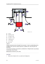
Gondola
A gondola is a streamlined pod mounted under the hull of the ship. It can either be
welded or bolted under the hull plates. It is well suited for refitting a vessel with an
EM 712 system.
There is a gap between the gondola and
the hull. Aerated water will pass through
this gap, and thus not be pushed under the
transducer.
This is often the preferred installation
approach for Kongsberg Maritime and the
method that gives the optimum weather
window and system performance.
The gondola can be tailored to fit the ship
and also the scope of supply.
Kongsberg Maritime recommends to place
a "debris knife" in the forward end of the
gondola.
The gondola will be water filled. To let the
air escape, make suitable holes in the rear
end close to the vessel’s hull.
A gondola installation may help in avoiding air bubble blockage of the sound path under
the transducers by aerated water. Gondolas may also contain additional transducers
for other systems.
Note
The inside surface of the gondola must be protected with appropriate protective paint
and an adequate amount of sacrificial anodes.
The installation shipyard must provide all necessary installation drawings.
If required, all drawings and documents must be approved by the vessel’s national
registry and corresponding maritime authority and/or classification society.
Such approval must be obtained before the installation can begin. The shipowner
and shipyard doing the installation are responsible for obtaining and paying for such
approval.
Kongsberg EM 712 Installation manual
Summary of Contents for EM 712
Page 71: ...401027 B 71 216148 EM 712 Transducer TX1 dimensions Drawing file ...
Page 72: ...72 401027 B Kongsberg EM 712 Installation manual ...
Page 73: ...401027 B 73 221048 EM 712 Transducer TX2 dimensions Drawing file ...
Page 74: ...74 401027 B Kongsberg EM 712 Installation manual ...
Page 75: ...401027 B 75 219621 EM 712 Transducer RX1 dimensions Drawing file ...
Page 76: ...76 401027 B Kongsberg EM 712 Installation manual ...
Page 77: ...401027 B 77 216146 EM 712 Transducer RX2 dimensions Drawing file ...
Page 78: ...78 401027 B Kongsberg EM 712 Installation manual ...
Page 79: ...401027 B 79 223137 EM 712 Transducer mounting frame 0 5 degrees Drawing file ...
Page 80: ...80 401027 B Kongsberg EM 712 Installation manual ...
Page 81: ...401027 B 81 223139 EM 712 Transducer mounting frame 1 degree Drawing file ...
Page 82: ...82 401027 B Kongsberg EM 712 Installation manual ...
Page 83: ...401027 B 83 223273 EM 712 Transducer mounting frame 2 degrees Drawing file ...
Page 84: ...84 401027 B Kongsberg EM 712 Installation manual ...
Page 85: ...401027 B 85 317812 EM 712 Casing w mounting frame 0 5 degrees Drawing file ...
Page 87: ...401027 B 87 375817 EM 712 Combined casing w mounting frame 1 degree Drawing file ...
Page 89: ...401027 B 89 396402 EM 712 Transmitter Unit dimensions Drawing file ...
Page 91: ...401027 B 91 396428 EM 712 Receiver Unit dimensions Drawing file ...
Page 92: ...92 401027 B 385422 Processing Unit dimensions Kongsberg EM 712 Installation manual ...
Page 93: ...401027 B 93 378828 Hydrographic Work Station dimensions Drawing file ...
Page 94: ...94 401027 B Kongsberg EM 712 Installation manual ...
Page 95: ...401027 B 95 371591 Rack installation kit dimenisons Drawing file ...
Page 96: ...96 401027 B 370275 Remote Control Unit K REM dimensions Kongsberg EM 712 Installation manual ...
Page 97: ...401027 B 97 Drawing file ...
Page 163: ...401027 B 163 Certificates IEC 60945 IACS E10 Technical specifications ...
Page 177: ...401027 B 177 7 Observe the handling rules for transducers Equipment handling ...
Page 188: ... 2018 Kongsberg Maritime ...


