background image

Equipment handling

• If any units are damaged, prepare an inspection report stating the condition of the

unit and actions taken. Describe the damage and collect photographic evidence if
possible. Re-preserve the equipment.

• If the units are not damaged, check the humidity absorbing material. If required,

dry or replace the bags, then re-pack the unit(s) according to the packing
instructions.

7

If the crate has been opened, make sure that is it closed and sealed after the
inspection. Use the original packing material as far as possible.

8

The storage room/area must be dry, with a non-condensing atmosphere. It must
be free from corrosive agents.

9

The storage area’s mean temperature must not be lower than -30° C, and not warmer
than +70° C. If other limitations apply, the crates will be marked accordingly.

10

The crate must not be exposed to moisture from fluid leakages.

11

The crate must not be exposed to direct sunlight or excessive warmth from heaters.

12

The crate must not be subjected to excessive shock and vibration.

13

If the unit contains normal batteries, these may have been disconnected/isolated
before the unit was packed. These must only be reconnected before the installation
starts. Units containing batteries are marked.

Caution

Units containing lithium or alkaline batteries must be handled separately
and with care. Such units are marked accordingly. Do not attempt to
recharge such batteries, open them or dispose of them by incineration.
Refer to the applicable product data sheets.

Unpacking

General unpacking procedure

Normal precautions for the handling, transportation and storage of fragile electronic
equipment must be undertaken.

Note

If the unit is not to be prepared for immediate use, you may consider storing it unopened
in its original packing material. However, it may be useful to open the case to check its
contents for damage and retrieve any accompanying documentation.

Do not use a knife to open cardboard cartons - the contents may lie close to the surface,
and may be damaged by the blade.

1

Check the carton before opening it to ensure it shows no signs of dropping,
immersion in water or other mishandling. If the carton shows signs of such damage,
refer to the paragraph covering Inspection on receipt.

397128/C

107

Summary of Contents for ACS500

Page 1: ...INSTRUCTION MANUAL ACS500 Acoustic Control System Gisma testport system...

Page 2: ......

Page 3: ...Kongsberg ACS500 Acoustic Control System Instruction Manual Gisma test port system 397128 C July 2016 Kongsberg Maritime AS...

Page 4: ...ithout the written approval from Kongsberg Maritime AS Disclaimer Kongsberg Maritime AS endeavours to ensure that all information in this document is correct and fairly stated but does not accept liab...

Page 5: ...Installing the Subsea Control Unit 20 INSTALLING THE SUBSEA TRANSDUCER 21 Installing the subsea transducer 21 CABLE LAYOUT AND INTERCONNECTIONS 23 Cable plan 24 List of cables 26 Cable procedures 27 C...

Page 6: ...ery level 45 Battery status Acoustic Command Unit 45 Battery status Subsea Control Unit 45 External battery capacity 45 User settings 46 Setting the telemetry power level for the ACU 46 Setting the te...

Page 7: ...th HiPAP 72 MAINTENANCE 74 Acoustic Command Unit 75 Cleaning the Acoustic Command Unit 75 Charging the Acoustic Command Unit 75 Changing the battery on the Acoustic Command Unit 76 Dunking transducer...

Page 8: ...97 Subsea Control Unit battery 97 Subsea Control Unit top end cap 97 Subsea Control Unit vent screw for top end cap 97 Subsea Control Unit maintenance kit for top end cap 98 Subsea Control Unit brack...

Page 9: ...utline dimensions 112 Subsea Control Unit outline dimensions 113 Subsea Control Unit arrangement 114 Subsea Control Unit bracket 115 TDR30V 34GT Subsea transducer outline dimensions 116 External quad...

Page 10: ...ve opens 130 Opening a transponder with defect possible defect battery 131 Opening a functioning transponder 131 Handling heated or warm separate battery 131 Handling transponders and separate transpo...

Page 11: ...ngsberg ACS500 Registered trademarks Windows Windows XP and Windows 7 are either registered trademarks or trademarks of Microsoft Corporation in the United States and or other countries HIPAP is a reg...

Page 12: ...to familiarize yourself with the Kongsberg ACS500 Topics System description on page 11 System diagram on page 12 System units on page 14 List of parts on page 16 General supply conditions on page 16...

Page 13: ...n ACS500 is designed for optimal control of subsea valves and is rated to 4000 metre depth ACS500 may be used to control an blow out preventer system as an emergency system or other subsea valve contr...

Page 14: ...Kongsberg ACS500 System diagram A standard ACS500 system diagram is provided System with y split cable 12 397128 C...

Page 15: ...ACS500 System with interface cables 397128 C 13...

Page 16: ...h proof portable case The ACU has an internal rechargeable battery with approximately 10 hours of continuous operation on a fully charged battery The customer also have the option of using the ACU as...

Page 17: ...lectric signal applied to the transducer Subsea Control Unit The SCU is the unit controlling the subsea valves Commands are sent from the ACU via the transducers and sent from the SCU to the valves Fi...

Page 18: ...nt during unpacking All equipment must be inspected for physical damage i e broken controls and indicators dents scratches etc during unpacking If any damage to the equipment is discovered the recipie...

Page 19: ...s been installed onto Unless other arrangements have been made in the contract the Kongsberg ACS500 guarantee period as specified in the contract begins when the acceptance documents have been signed...

Page 20: ...necessary to plan the installation of the Kongsberg ACS500 according to Kongsberg Maritime s requirements Correct installation is vital to the system performance See your registration form for all pa...

Page 21: ...try and corresponding maritime authority and or classification society The shipowner and shipyard performing the installation are responsible for obtaining and paying for installation approval Kongsbe...

Page 22: ...the SCU Procedure 1 The SCU comes secured on a mounting bracket See the Drawing file on page 110 Mount the bracket onto the valve control structure by the hooks behind the SCUs The bracket is constru...

Page 23: ...e sides of the valve package and must be positioned such that they have a clear line of sight to the surface They should be located as far away from the valve structure and other reflective surfaces a...

Page 24: ...Kongsberg ACS500 4 Tighten the bolts to the torque recommended by the bolt manufacturer If A4 or similar bolts are used tighten the bolts to a torque of 40 Nm 22 397128 C...

Page 25: ...ons Cable layout and interconnections This chapter provides the cable plan and cable installation requirements for the Kongsberg ACS500 Topics Cable plan on page 24 List of cables on page 26 Cable pro...

Page 26: ...Kongsberg ACS500 Cable plan Observe the cable plan for Kongsberg ACS500 All cables are provided from Kongsberg Maritime System with y split cable 24 397128 C...

Page 27: ...erconnections System with interface cables A Dunking transducer with cable drum B Acoustic Command Unit C Subsea Control Unit D Subsea Transducer E Customer valve package F Quad battery pack G Field s...

Page 28: ...Subsea Control Unit and is 2 metres long C5 Subsea battery cable optional This cable is identical to C4 C6 Transducer test cable This cable is for testing in air is 50 metres long and on a cable drum...

Page 29: ...purposes and to allow for vibration make sure that some slack is provided for each cable Topics Connecting the cable from the Subsea Control Unit to the external quad battery unit option on page 28 C...

Page 30: ...y to prevent the cables being damaged 4 Connect the cable to the SCU as indicated Connect the other end to the external battery unit These are cables ACS500 C4 and ACS500 C5 Connecting the transducer...

Page 31: ...ect the cable to the SCUs as indicated Connect the other end to the valve package This is cable ACS500 C10 Connecting the interface cable from the Subsea Control Unit to the valve package Purpose This...

Page 32: ...drum on page 30 Starting operation on page 31 Dunking transducer with cable drum A Locking clip open B Bars C Locking clip closed D Cover E Cable connection 1 5 metres F Handle G Drum lock Opening th...

Page 33: ...ace the transducer in the basket 6 Lock the transducer cable by pushing the drum lock G in 7 Fold in the handle F 8 Press the two bars B together and press the locking clip C into position Starting op...

Page 34: ...edure 1 Place the ACU in a suitable location and open the lid by pressing the handle knobs and pulling the handles towards you 2 Turn on the ACU with the Power button D on the right hand side The syst...

Page 35: ...page 48 3 In the SCU Solenoid Information section tap the function you want to execute 4 Press Execute F on the left side of the ACU and tap Execute N on the touch screen at the same time 5 Observe th...

Page 36: ...Kongsberg ACS500 Acoustic Command Unit This chapter contains detailed descriptions of the ACS500 control panel 34 397128 C...

Page 37: ...e with the Emergency button to start an emergency sequence G Trackball and mouse controls for operational use H This will only turn off the computer the hardware will still drain the battery Use butto...

Page 38: ...Kongsberg ACS500 ACU Computer buttons on page 37 User interface on page 38 36 397128 C...

Page 39: ...puter off without saving any changes Use the Power button D Power button and battery level The battery level indicator M shows you how much battery power is left A green LED is lit when you have full...

Page 40: ...Status on page 40 Battery status on page 40 Sensor Input on page 41 More Status on page 41 Help on page 42 Subsea Telemetry Power on page 42 Execute on page 42 SCU Solenoid Information on page 42 Exi...

Page 41: ...mplete system Menu bar SCU 1 and SCU 2 are the operational menus for the two Subsea Command Units and are explained in detail in Operational procedures on page 43 Operation Log is where all commands a...

Page 42: ...igure the different options in your system System Status Tap Read to see the system status It is important to know the status of the system before executing any commands Battery status Tap Read to see...

Page 43: ...he reading comes up and the colour of the field indicates if the values are within the set parameters Alarm conditions are shown in red and a dialogue comes up with the alarm details More Status Tap M...

Page 44: ...Choose between Minimum Low High and Maximum Tap Set to confirm the setting Execute Execute is used for valve operation and in the two hands two buttons emergency system SCU Solenoid Information This s...

Page 45: ...ge 51 Messages on page 54 Valve operation Purpose This procedure shows how to start up the subsea system The system is delivered with the batteries separate as a safety precaution Procedure 1 Select t...

Page 46: ...n is done Dark green The valve operation is done and the system has sent a warning the warning is displayed by the valve symbol Low battery or High currents are examples of warnings Red An error happe...

Page 47: ...ed when the battery is almost empty See Acoustic Command Unit on page 34 Battery status Subsea Control Unit Purpose This procedure helps you find the battery level of the SCU Procedure 1 In the ACU ta...

Page 48: ...n page 47 Changing between Cymbal and FSK on page 47 Setting the telemetry power level for the ACU Purpose This procedure explains how to change the power level for the ACU Procedure You should always...

Page 49: ...er level on 2 In the Subsea Telemetry Power section use the arrows to change the power setting 3 Tap Set to confirm the setting 4 A telemetry dialogue will come up and show if the power level is chang...

Page 50: ...e step at the time on both the ACU and the SCU See Setting the telemetry power level for the ACU on page 46 and Setting the telemetry power level for the Subsea Control Unit on page 47 Check the commu...

Page 51: ...sors are checked and listed When the values are within the predefined parameters the slot is green When the values are outside the limits you receive an alarm message Reading the software versions Pur...

Page 52: ...quence that can be performed in the event of Windows not working Procedure 1 Unscrew the button on the emergency button cover E 2 Observe the LEDs inside if the Run LED is red you have an error The em...

Page 53: ...the session Auto Shutdown option The Auto Shut Down system is a predefined automated shutdown sequence When the sensors are in a predefined state the system will close the predefined valves in a prede...

Page 54: ...ce in the example with 4 single valve operations will be executed directly after triggering from the sensors from SCU 1 The SCU 2 will perform a defined delay before starting the ASHD valve sequence t...

Page 55: ...Operational procedures The main window in the ACU will display information about the Auto Shutdown status The status window will either show Auto Shutdown as Enabled or Disabled 397128 C 53...

Page 56: ...o status reply after execution of a valve on page 65 Case 4 Trying to activate the Arm function twice on page 66 Case 5 Executing a Disarm function when a valve function is still active on page 66 No...

Page 57: ...rigger an active valve directly Check for sensor failure Analogue sensor error detected SCU error bit message regarding Analogue Sensor connection Check the SCU BOP Interface and Sensor Current low li...

Page 58: ...essage is displayed then the SCU is not allowed to perform a Valve operation towards the solenoids Try to read the actual current value in More Status Check battery status If possible check the other...

Page 59: ...enient for battery change Sensor input Output values available may be configured in different ways mA Psi etc Normal current sensor values should be in the area of 4 to 20 mA The background colour wil...

Page 60: ...eakage value Valve operation messages Message Description Action Press execute buttons When choosing a Valve function we get this message in order to proceed in the process Press the two Execute butto...

Page 61: ...ll be updated with a warning message Check current reading valve in More status If the valve is significantly outside the defined scope then check the SCU system Unknown This valve has not been operat...

Page 62: ...fore checking out the problem Possible solution Repeat the DISARM function in order to reset all Valves Not armed Force red colour Text and colour when main status of SCU has discovered an VALVE ERROR...

Page 63: ...nt detected Check SCU function if repetition of the message then prepare for service exchange of unit Low battery Status message bit from SCU Low battery event detected Check Battery status remaining...

Page 64: ...ed Current overflow Caution Fatal Error detected SCU will not execute the Valve function due to current overflow in the system in order to protect the SCU electronics and the solenoids Try to read the...

Page 65: ...e is not within specified window showing either a Low or High current warning The actual current value may be checked in the More Status menu Valve 5 ARM and DISARM functions were executed OK When try...

Page 66: ...ed from the SCU Valve 5 execution is stopped with a yellow warning Valve already executed Force This message occurs when the previous status from the readback sensor in the SCU is that Valve 5 is alre...

Page 67: ...U giving a warning Timeout Force Note In a critical operational phase we may still try to execute the function in Cymbal only regarding timeout window setup values without receiving any status read ba...

Page 68: ...readback sensor indicates that the valve package is already armed This is only a yellow warning Press and tap both execute buttons for 5 seconds in order to perform the function Case 5 Executing a Dis...

Page 69: ...ue to unwanted execution of the active valves in the system When trying to execute the DISARM function when ARM sensor is not Active we get a red background for status Not armed Force on the valve DIS...

Page 70: ...S500 Simulation and test This chapter describes the test procedures for the ACS500 system Topics Connecting the test equipment on page 70 Test procedure on page 70 Testing ACS500 with HiPAP on page 72...

Page 71: ...Simulation and test 397128 C 69...

Page 72: ...rred method Purpose This procedure shows how to set up the test system Procedure 1 Disconnect the subsea transducer from the SCU 2 Connect the transducer test cable to the SCU 3 Connect the other end...

Page 73: ...When the LED is switched off check that the correct status message is displayed on the ACU screen FAILURE is displayed if something is wrong 6 Continue with the ARM function if available Tap ARM and...

Page 74: ...Kongsberg ACS500 Testing ACS500 with HiPAP Testing the system is also possible using HiPAP 72 397128 C...

Page 75: ...Connect the transducer patch cable 2 Lower the dunking transducer into water Caution Make sure there are no obstacles between the dunking transducer and the HiPAP transducer 3 Operate the system from...

Page 76: ...the main units Note Major repairs and complete overhaul of the Kongsberg ACS500 can only be done by an authorized Kongsberg Maritime service engineer Topics Acoustic Command Unit on page 75 Dunking t...

Page 77: ...cloth moistened in fresh water Do not use strong solvents Dedicated cleaning chemicals for displays are provided by office suppliers Charging the Acoustic Command Unit Purpose This procedure explains...

Page 78: ...pends on use and battery maintenance Procedure 1 Detach the supports on either side of the lid by unscrewing one screw on each side 2 Unscrew 18 screws on the front panel 3 Lift the monitor from the c...

Page 79: ...nsducer Purpose This procedure explains how to check the dunking transducer for defects Procedure 1 Ensure that the transducer face is clean and free of defects 2 Check that the retaining strap is in...

Page 80: ...lastic scraper or a stiff brush not wire to remove shells and growth Be careful not to damage the paint as this leads to corrosion 2 Ensure that all dirt slime and growth is removed 3 Clean the unit t...

Page 81: ...vent screw and the top end cap itself when the lid has been opened See Testing the seal on page 89 Replace a Subsea Control Unit and duplicate the configuration Purpose This procedure explains how to...

Page 82: ...ou want to duplicate in the Replace SCU dialog box 10 Select communication port 11 Select report location 12 Select the Configure and Execute at the same time this is a two hand operation Wait while t...

Page 83: ...ert the new battery Inserting the battery at an angle makes it easier 4 Place the top end cap back on Observe the alignment marks on the lid and the body of the SCU Follow the open procedure in revers...

Page 84: ...to identify the interseal test ports to verify that the SCU is properly sealed and watertight Related topics Interseal test on page 88 Important Before you apply pressure make sure that all connection...

Page 85: ...testing see Testing the seal on page 89 External quad battery unit for the Subsea Control Unit Maintenance on the quad battery unit is mostly changing the battery and checking the seals before the un...

Page 86: ...e unit before opening it Procedure 1 Use a wooden or plastic scraper or a stiff brush not wire to remove shells and growth 2 Ensure that all dirt slime and growth is removed 3 Clean the unit thoroughl...

Page 87: ...t on the test port D when the lid has been opened See Testing the seal on page 89 Changing the batteries in the external quad battery unit Purpose This procedure explains how to change the battery on...

Page 88: ...growth on the transducers will degrade the system s operational capabilities Clean the transducers at every opportunity Procedure 1 Use a wooden or plastic scraper or a stiff brush not wire to remove...

Page 89: ...bolts are not delivered with the transducer as they depend on the thickness and material of the structure they are mounted on 10 Tighten the bolts to the torque recommended by the manufacturer 11 Run...

Page 90: ...nnect to Digital pressure indicator C Volume adjuster D Limit adjuster E Scissor action handles F Outlet port connect to unit to be tested G Selector valve H Pressure relief valve Assemble the test ki...

Page 91: ...essure indicator user manual Druck PV411A Hand pump user manual Assemble the test kit on page 88 Important Before you apply pressure make sure that all connections are correct and that all equipment a...

Page 92: ...This verifies that the seal is undamaged 12 Open the selector valve G carefully to remove the pressure by turning counterclockwise Changing the battery in the Digital pressure indicator Purpose This p...

Page 93: ...Maintenance 4 Connect a new 9 volt battery and assemble everything in the reverse order 397128 C 91...

Page 94: ...ne replaceable units are defined Additional spares are also identified Topics Line replaceable units on page 93 Ordering spare parts on page 94 Acoustic Command Unit spare parts on page 94 Dunking tra...

Page 95: ...ned as line replaceable units for the SCU Subsea Control Unit Complete unit Battery Top end cap Complete top end cap with O rings Vent screw Complete with O ring Top end cap maintenance kit All O ring...

Page 96: ...nits printed circuit boards and software the vessel name is also useful as this allows us to update our vessel database Acoustic Command Unit spare parts All spare parts for the ACU are listed here Ac...

Page 97: ...arts All spare parts for the dunking transducer are listed here Dunking transducer line replaceable units on page 95 Dunking transducer complete unit on page 95 Dunking transducer line replaceable uni...

Page 98: ...spare parts for the SCU are listed here Subsea Control Unit line replaceable units The following parts have been defined as line replaceable units for the SCU Subsea Control Unit Complete unit Battery...

Page 99: ...form for part number information Subsea Control Unit battery Item information Part name Lithium battery pack Part number 319554 Subsea Control Unit top end cap Item information The top end cap is del...

Page 100: ...cable Item information Part name Y split cable Gisma 37 pins connector YC G37T 2 11 G37T Part number 336621 Part name Y split cable Gisma 37 pins connector YC G37T 2 5 G37T Part number 392179 Part nam...

Page 101: ...8 G37T Part number 394986 Subsea Control Unit serial line cable Item information Part name SL A6 5 G7T Part number 397127 Subsea Control Unit sealing cap for 7 pins connector Item information Part nam...

Page 102: ...ete unit Item information Part name Subsea transducer TDR30V 34GT Part number 336611 Subsea transducer transducer cable Item information Part name Transducer cable XC G7T 15 G7T Part number 336622 Tes...

Page 103: ...mulator test cable Part number Customer specific see the registration form Patch cable for testing with HiPAP Item information Part name Patch cable Part number 336625 Transducer test cable Item infor...

Page 104: ...nit may be any large or small part of the system It can be supplied as part of the initial delivery or as a spare part Topics Disposal on page 103 Inspection on page 103 Lifting on page 103 Re packagi...

Page 105: ...bserve the relevant Waste Electrical and Electronic Equipment WEEE regulations Inspection An inspection must be carried out immediately after the unit s have arrived at their destination 1 Check all w...

Page 106: ...ontainer by appropriate shock absorbing insulation polystyrene foam chips etc Large units must be placed in a suitable cardboard box or wooden crate The unit must be protected against physical damage...

Page 107: ...areas must be cleaned prepared and preserved using the correct preservation mediums for the unit The mediums to be used will usually be defined in the units maintenance manual 3 Open the unit and usi...

Page 108: ...the electronic components as dry as possible Coatings Spray the unit externally with a corrosion inhibitor e g a light oil before packing Storage prior to installation or use When a system a unit or...

Page 109: ...If the unit contains normal batteries these may have been disconnected isolated before the unit was packed These must only be reconnected before the installation starts Units containing batteries are...

Page 110: ...ls door keys etc Unpacking electronic and electromechanical units Electronic and electromechanical units will normally be wrapped in a clear plastic bag Lift the unit in its bag out of the carton and...

Page 111: ...s must be investigated by the packer shipper before the unit is dispatched All local transportation must be carried out according to the same specifications as for the initial delivery In general all...

Page 112: ...e available on PDF and or AutoCad s DWG format Dunking transducer unit outline dimensions on page 111 Acoustic Command Unit outline dimensions on page 112 Subsea Control Unit outline dimensions on pag...

Page 113: ...Drawing file Dunking transducer unit outline dimensions 397128 C 111...

Page 114: ...Kongsberg ACS500 Acoustic Command Unit outline dimensions 112 397128 C...

Page 115: ...Drawing file Subsea Control Unit outline dimensions 397128 C 113...

Page 116: ...Kongsberg ACS500 Subsea Control Unit arrangement 114 397128 C...

Page 117: ...Drawing file Subsea Control Unit bracket 397128 C 115...

Page 118: ...Kongsberg ACS500 TDR30V 34GT Subsea transducer outline dimensions 116 397128 C...

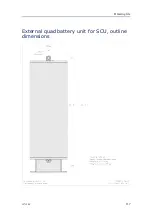
Page 119: ...Drawing file External quad battery unit for SCU outline dimensions 397128 C 117...

Page 120: ...Kongsberg ACS500 Simulator outline dimensions 118 397128 C...

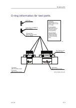
Page 121: ...o 336676 Lubricants Use Molykote 1 11 or Parker Super O Lube for O rings O ring handling Use O ring pick tool 372654 for gentle O ring handling Test port torque Tighthening torque for lubricated plug...

Page 122: ...g we are continuously working to improve the quality and performance of our products Technical specifications may therefore be changed without prior notice Topics Acoustic link on page 121 Performance...

Page 123: ...mpleted Two basic link principles are available in the UTB modems The optimal and fast Cymbal spread spectrum coherent acoustic link The well known non coherent FSK principle with a number of transmit...

Page 124: ...0 kHz to 26 5 kHz in steps of 250 Hz Wake up frequencies FSK Channel 76 24 and 23 5 kHz Wake up frequencies FSK Channel 86 24 5 and 23 5 kHz Max transmission power 300 W Common for transducers Operati...

Page 125: ...19 5 kg Dunking transducers Width 225 mm Height 500 mm Depth 590 mm Weight Approximately 25 kg TDR30V 34T Diameter 166 mm Height 212 mm Weight 15 kg External quad battery Diameter 304 mm Height 947 5...

Page 126: ...cells Lithium Battery output 14 VDC Total battery energy content Maximum 4 x 128 Ah Environmental specifications This section provides the technical specifications and requirements related to the envi...

Page 127: ...and separate lithium batteries Identification of the products and company Product name All Kongsberg transponders Subsea Control Units with a lithium battery and separate Kongsberg transponder lithium...

Page 128: ...port website http www km kongsberg com support_hpr Composition and information on chemicals Battery chemicals A transponder lithium battery consists of Lithium Metal cells with the formula Lithium Thi...

Page 129: ...nschein SL 780 Saft LS 33600 Saft LSH 20 Sonnenschein SL 760 Battery design A transponder lithium battery consists of several battery cells that are electrical connected both in serial and parallel Th...

Page 130: ...ide the transponder The transponder can explode if the inside pressure is high enough If the transponder explodes either the transducer or the bottom end cap will blow out or the transponder becomes f...

Page 131: ...al reactions fire will continue without additional supply of oxygen so extinguisher like Lith X will not work properly Applying water directly onto a battery may develop hydrogen gas due to the possib...

Page 132: ...emperature must be checked to verify a possible temperature increase in the lithium battery Failing and normal temperature Take out the battery see Opening a transponder with defect possible defect ba...

Page 133: ...ction equipment Caution Do not stand in front of transducer or bottom end cap when opening the transponder If there has been water ingression and the battery is still warm Disconnect the battery from...

Page 134: ...stored indoors The battery must be removed from the transponder when stored indoors Storage temperature Recommended storage temperature lies between 0 C and 25 C max 50 C min 55 C Storage relative air...

Page 135: ...ity The products are stable under normal conditions see Hazards identification on page 127 Toxicological information Signs and symptoms None unless battery ruptures In the event of exposure to interna...

Page 136: ...be shipped in accordance with the prevailing national regulations Transponder with lithium battery UN no 3091 Class 9 Miscellaneous Lithium batteries contained in equipment Separate transponder lithi...

Page 137: ...afety procedures Other information The battery cell manufacturers safety data sheets are available on the following internet addresses Saft www saftbatteries com Tadiran Sonnenschein www tadiranbatter...

Page 138: ...Kongsberg ACS500 Appendix A Type approval certificate 136 397128 C...

Page 139: ...Appendix A Type approval certificate 397128 C 137...

Page 140: ...Kongsberg ACS500 138 397128 C...

Page 141: ...Appendix A Type approval certificate 397128 C 139...

Page 142: ...Kongsberg ACS500 140 397128 C...

Page 143: ...h GISMA foam cleaner Allow three minutes to react In case of strong dirt repeat the procedure Then rinse with clean water Following rinse with the enclosed cleaning liquid to neutralize foam cleaner 3...

Page 144: ...g gegen die Einbaudose Schottdurchf hrung oder Druckk rperdurchf hrung geschraubt werden Besitzt die berwurfmutter eine Blockierschraube so muss diese angezogen werden After tightening the coupling nu...

Page 145: ...r change battery 90 Disposal equipment 103 DNV certificate 137 drawing simulator outline dimensions 118 Drawing ACU outline dimensions 112 dunking transducer outline dimensions 111 O rings for test po...

Page 146: ...Maintenance 74 procedures 74 Maritime authority approval 19 Mechanical drawings 110 Menu bar 39 More status 41 N Normal operation 33 43 Valves 33 43 O Online help 42 Open quad battery 84 Open SCU 78 O...

Page 147: ...ea Command Unit cloning 79 duplication 79 Subsea Control Unit change battery 81 installation 20 Line replaceable units 93 96 open 78 Power level 47 Subsea telemetry power 42 Subsea transducer change 8...

Page 148: ...2016 Kongsberg Maritime...

Reviews: