background image

Instruction manual SMV 10 600B – 60 1500B Publ. no. 6196.082 1117, Version 02

57

Service and maintenance

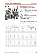
RETIGHTENING OF BOLT JOINTS, TORQUE

In order to choice exactly the correct torque, information
about the friction conditions is required.

WARNING
It is important that the torque of the bolt joints 
is regularly checked. 
It is in particularly important that all bolts are 
checked at the "first service".

WARNING
The torque of the wheel nuts must be checked 
daily for the first 14 days, or until the wheels, 
clamps and nuts have been tightened and no 

further retightening is possible. This must be done:
• after new delivery of a machine
• after first use of the machine
• after the removal or replacement of a wheel

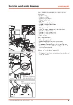
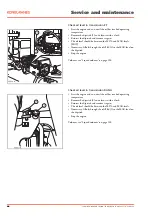
The bolt joints described on the following pages are to be tightened 
with a torque wrench.

The chart below states the torque for bolts "slightly lubricated".

Metric thread

UTS thread

Thread

M

Strength classification

Thread

UNC

Strength classification

8.8

Nm

10.9

Nm

12.9

Nm

8.8

Nm

10.9

Nm

12.9

Nm

6

9.8

14

17

1/4"

11

15

19

8

24

33

40

5/16"

22

31

38

10

47

65

79

3/8"

38

54

68

12

81

114

136

7/16"

61

87

108

14

128

181

217

1/2"

93

131

163

16

197

277

333

9/16"

133

187

234

18

275

386

463

5/8"

183

259

323

20

385

541

649

3/4"

322

455

568

22

518

728

874

7/8"

516

729

909

24

665

935

1,120

1"

772

1,090

1,360

27

961

1,350

1,620

1 1/8"

1,090

1,550

1,930

30

1,310

1,840

2,210

1 1/4"

1,530

2,160

2,690

33

1,770

2,480

2,980

1 3/8"

2,020

2,850

3,550

36

2,280

3,210

3,850

1 1/2"

2,650

3,750

4,680

Summary of Contents for SMV 10-1200B

Page 1: ...ction manual SMV 10 600B 60 1500B Publ no 6196 082 1117 Version 02 1 Model range SMV 10 600B SMV 60 1500B Instruction manual SMV 10 600B 60 1500B Publ no 6196 082 1117 Version 02 CONDESIGN INFOCOM AB...

Page 2: ...y repairs please only use Konecranes Lifttruck original spares This is a prerequisite for ensuring that your machine from Konecranes Lifttrucks shall maintain its original technical standard When orde...

Page 3: ...of the hydraulic system 50 Wheel replacement 50 Retightening of bolt joints torque 57 Overview lubrication schedule 62 Engine oil oil filter and oil cleaner Scania 64 Fuel system Scania 66 Engine oil...

Page 4: ...nents It is not allowed to bring along passengers Lifting persons with the machine is prohibited Never exceed the lifting capacity of the machine see the type plate and load chart The load must always...

Page 5: ...sonal injury if regulations are not followed TAKE CARE Situation that may lead to damage to the product if regulations are not followed Always read the instructions that follow the warning symbol or i...

Page 6: ...hin the work area can only be guaranteed if the machine is used correctly If tendencies of tipping over occur due to prohibited manoeuvres or incorrect driving the instructions given must be adhered t...

Page 7: ...sing electrical energy The axial piston pumps together with a gear pump are fitted directly on the transmission The gear pump builds up the accumulator pressure for the foot and parking brakes The var...

Page 8: ...0 1500B Publ no 6196 082 1117 Version 02 Presentation of the machine OVERVIEW OF THE MACHINE 1 Mast 2 Fork carriage 3 Forks 4 Tilt cylinder 5 Lift cylinder 6 Drive axle 7 Engine hood 8 Steering axle 9...

Page 9: ...no 6196 082 1117 Version 02 9 Presentation of the machine ID PLATES AND SERIAL NUMBER 1 Mast number 2 Load capacity plate 3 Fork carriage number 4 Driving axle number 5 Chassis number 6 Transmission n...

Page 10: ...washer 7 Adjustment lever steering wheel 8 Control levers hydraulics 9 Accelerator pedal 10 Brake pedal 11 Declutch 12 Cooling AC 13 Recirculation 14 Heater controls 15 Fan 16 Instrument panel and sw...

Page 11: ...9 Hazards 10 Rotating warning lights 11 Lever steering optional 12 Central lubrication optional 13 Central lubrication optional 14 Activation diagnostics engine optional 15 Ignition lock 16 Emergency...

Page 12: ...overview of the activities of the machine during operation 1 Lever steering active optional 2 Low coolant level optional 3 Warning low fuel level 4 Low battery power 5 Low oil pressure engine 6 Parki...

Page 13: ...of maximum fuel consumption Engine type Current fuel consumption litres hour Average fuel consumption litres hour Operational time since last reset Estimated fuel consumption F4 litres Total amount o...

Page 14: ...ional Press F3 on the start page The hydraulics page shows Pressure lift cylinder Tilt angel Height indicator Weight Last added weight Total added weight Weight calibration without load Weight calibra...

Page 15: ...o previous page Settings page Press F3 on the adjustment and measuring page The settings page shows F1 Shows display settings F2 Shows the page for setting date and time F3 Shows language settings pag...

Page 16: ...ge is shown when the electronic register input data from sensors etc are outside the permitted ranges Low error or High error The message indicates sensor fault cable fault or input fault on module Th...

Page 17: ...miter with blocking 6 Position 1 lever to the right is full suspension Position 2 one step to the left is limited suspension Position 3 two steps to the right is blocking delivery position Adjust the...

Page 18: ...Activate the declutch using the foot switch 2 If the switch is pressed further together with the pedal the brakes are applied further When braking only with the brake pedal 3 the disconnection is onl...

Page 19: ...ne EMERGENCY STOP When using the emergency brake press button 1 downwards all functions are switched off The parking brake is activated and the engine stops WARNING There is a risk of tipping when usi...

Page 20: ...tor Switch on the cooling and set the cold temperature to the desired position During autumn and early winter with high air humidity with rain slush and mist on the windows Switch on the cooling Open...

Page 21: ...space there there is a pump for the tilting with a pump handle When tilting upwards the valve is turned clockwise downwards counter clockwise using the bottom end of the pump handle Fit the pump hand...

Page 22: ...buzzer F5 7 5 A Condenser F6 7 5 A Driving light main beam F7 7 5 A Driving light dipped beam F8 10 A IQAN MD3 MDL F9 10 A IQAN XS2 F10 10 A IQAN XA2 B0 F11 10 A IQAN XA2 B1 F12 7 5 A Hazard lights c...

Page 23: ...he machine F30 5 A Work light roof F31 10 A Unit ELME F32 5 A Electrically heated rear view mirror F33 Extra F34 Extra F35 15 A Extra F36 15 Extra F37 10 A Computer F38 10 A Computer reversing camera...

Page 24: ...of electric shock and personal injuries jewellery and other conducting material must always be removed prior to working on the electrical system of the machine The power may only be cut with the main...

Page 25: ...5 Work light roof K6 Work light extra K7 Reversing light K8 Driving direction selector K9 K10 Windscreen wiper rear K11 Windscreen wiper roof K12 Windscreen wiper front K13 Indicator light K14 K15 Sid...

Page 26: ...fume extraction Prior to running the engine the driving direction indicator 1 to the left of the steering wheel must be in neutral The parking brake must be activated 2 When starting Sit down in the...

Page 27: ...un with a continuously high load there is a risk of damage to the turbo and of overheating if the engine is stopped without allowing it to cool down Allow the engine to run without load for a few minu...

Page 28: ...the machine is to be driven on steeper slopes you should contact your Konecranes Lifttrucks dealer The hill climbing ability stated in the data sheet is based on the pulling ability of the machine and...

Page 29: ...ys start in first or second gear in order to avoid damage and to prevent the transmission from overheating Release the parking brake 2 Move driving direction indicator 1 forwards Release the brake ped...

Page 30: ...as a brake When the machine has stopped completely activate the hand parking 2 before you release the foot brake Place the driving direction indicator 1 in neutral H2194 A Driving forward changing dr...

Page 31: ...late on the left side of the cabin If optional equipment has been fitted read the capacity plate for this The values that are stated on the capacity plate applies to compact and regular load and if th...

Page 32: ...ght of the driver seat NOTE Pay attention to the operational symbols and the directional arrows 4 5 1 2 3 Raising of the fork carriage Pull the lever 1 backwards Lowering of fork carriage Move lever 1...

Page 33: ...the manoeuvre levers The directional valve is therefore equipped with a mechanical control that allows manual lowering DANGER Ensure that the carriage and the mast can be lowered without hindrance Ens...

Page 34: ...jury or fatality Never park or leave the machine with raised load unsupervised Do not drive with the load displaced sideways e g by side manoeuvring Transport the load close to the ground WARNING Avoi...

Page 35: ...ition Carefully push the forks under the load until the fork shafts touch the load Ensure that the centre of gravity of the load is in the middle between the forks Raise the stand until the load is re...

Page 36: ...ad as carefully or precisely as possible Raise the fork carriage to the correct height Place the mast vertically Carefully drive up to the stack Lower the load Carefully reverse from the stack Ensure...

Page 37: ...kes and must only be towing using a vehicle that has sufficient braking capacity to stop both vehicles Use the rear towing peg when fitting a sturdy towing pole on the machine Fix the other end of the...

Page 38: ...ine SMV 10 25 Fix lifting straps to the four anchor points indicated Fix two lifting straps to the rear lifting eyes 1 situated on each side of the counter weight Fix two lifting straps to the front l...

Page 39: ...fting eyes 2 situated in the upper cross beam of the outside stand Fit lifting straps to the lifting hook of the crane 3 BE CAREFUL When the lifting straps have been fixed to the hook the safety lock...

Page 40: ...e might be height restricted passages along the transport route Securing of the rear of the machine Activate the parking brake Place blocks by every wheel preventing movement forwards and backwards Ma...

Page 41: ...of the machine yourself we recommend that the first three customer service inspections are done in the presence of Konecranes Lifttrucks authorised personnel who can ensure that the maintenance instru...

Page 42: ...the control units before you reconnect the battery Correct procedure for jump starting BE CAREFUL It is prohibited to jump start using a quick charger booster power pack or similar It may cause power...

Page 43: ...e pressure condition and bolts of the wheels Functioning of brake system Functioning of the steering system Functioning of the hydraulic system Lights and horn Check engine oil level Lift up the inspe...

Page 44: ...MAX levels HOT If necessary fill oil through the refill lid 2 to the MAX level on the dipstick Stop the engine Volumes see Liquid volumes on page 100 Check oil level in transmission DANA Start the en...

Page 45: ...nsure that the oil level is between the MIN and MAX levels on the indicator on the side of the hydraulic oil tank the stand must be lowered Filling up hydraulic oil WARNING Hot hydraulic oil may squir...

Page 46: ...necessary fill with the recommended diesel fuel WARNING In order to avoid that air is sucked into the fuel injection system the fuel tanks should never be allowed to run dry If air enters the fuel sy...

Page 47: ...filter indicator Check the indicator 1 If the indicator shows RED replace the indicator by pressing button 2 on the unit Start the engine If the indictor still shows red stop the engine and clean or...

Page 48: ...d Always use necessary protective equipment Batteries generate explosive hydrogen gas when being charged Ensure good ventilation and avoid sparks The switch 1 is located on the right side of the machi...

Page 49: ...water etc does not penetrate during cleaning Clean in particular the areas around the oil filling and the lubrication points prior to service If a degreasing agent is used when cleaning ensure that th...

Page 50: ...For axel load see the technical data sheet In order to lift the machine driving shaft place the jack under the driving shaft 1 and block the wheels on the steering shaft In order to lift the machine...

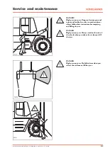
Page 51: ...serious personal injury and fatality In order to avoid accidents always follow these instructions for emptying and filling of tyres DANGER High pressure tyres Always stand on the side of the wheels wh...

Page 52: ...t be released via the valve or if there is doubt as to the functioning of the valve a hole must be drilled in the thread pattern DANGER High pressure tyres Always stand on the side of the wheels when...

Page 53: ...for the tyre in question If a safety cage is being used the tyre can be filled to full pressure If not the tyre must be filled to the fitting pressure stated by the tyre manufacture Do not exceed the...

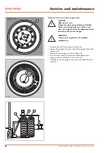
Page 54: ...the wedge band and the clamps may shoot loose when the pressure changes WARNING Only use tyres approved by the machine manufacturer Remove all nuts 2 and clamps 3 except two Support the weight of the...

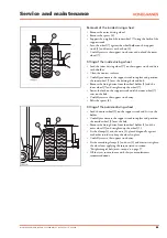
Page 55: ...vice from the wheel holder 1 and the inner wheel 7 and straighten up the wheel 7 Lower the fork on the support truck until the inner wheel 7 rests on the hub Carefully reverse the support truck away R...

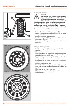
Page 56: ...of the steering wheel 10 using the fork of the support truck Remove the remaining nuts and clamps Lean the steering wheel 10 against the wheel holder 1 and fixate it with a chain 8 Carefully reverse...

Page 57: ...st use of the machine after the removal or replacement of a wheel The bolt joints described on the following pages are to be tightened with a torque wrench The chart below states the torque for bolts...

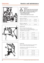
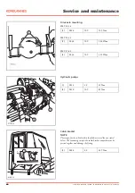
Page 58: ...ft SMV 10 16 M22 x 1 5 10 9 650 Nm SMV 18 60 M18 x 2 10 9 350 Nm Wheel nuts steering shaft Steering axle M22 x 1 5 8 8 400 Nm Engine mounts Check the condition of the rubber mounts If any wear is disc...

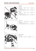
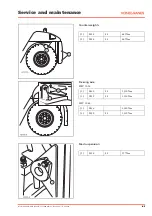
Page 59: ...ft SMV 10 18B Towards transmission 1 M12 8 8 81 Nm Towards drive axle 2 M12 8 8 81 Nm SMV 28B Towards transmission 1 M12 8 8 81 Nm Towards drive axle 2 M14x2 8 8 128 Nm SMV 32 60B Towards transmission...

Page 60: ...M24 10 9 935 Nm SMV 18 33 1 M 30 10 9 1 840 Nm SMV 37 60 1 M 36 10 9 3 210 Nm Hydraulic pumps 1 M12 8 8 81 Nm 2 M10 10 9 65 Nm Cabin bracket NOTE The torque for the cabin bracket should not exceed the...

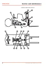
Page 61: ...no 6196 082 1117 Version 02 61 Service and maintenance Counter weights 1 M24 8 8 665 Nm 2 M24 8 8 665 Nm Steering axle 1 M30 8 8 1 310 Nm 2 M20 8 8 1 310 Nm SMV 10 16 1 M36 2 280 Nm 2 M30 8 8 1 310 Nm...

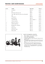
Page 62: ...62 Instruction manual SMV 10 600B 60 1500B Publ no 6196 082 1117 Version 02 Service and maintenance OVERVIEW LUBRICATION SCHEDULE...

Page 63: ...filter SCANIA H1976 A page 66 16 Water separator H1894 A page 66 Instruction manual SMV 10 600B 60 1500B Publ no 6196 082 1117 Version 02 63 Service and maintenance General rules applicable to lubrica...

Page 64: ...that the seal is not damaged Replace if necessary Refit the drain plug Tighten the drain plug WARNING The engine oil may be hot Danger of personal injury Carefully open the lid to avoid burns Replacem...

Page 65: ...ng If the deposits are thicker than 20 mm clean more often Clean all parts in diesel oil Return the o ring 3 inside the cover It must not be damaged Replace if necessary Filling up engine oil Remove t...

Page 66: ...l the seal comes into contact with the cover Then tighten the filter another 1 2 turn by hand Bleed the fuel system Close the engine hood After a test drive make sure that there are no leaks BE CAREFU...

Page 67: ...a clean container with fuel Open the bleeding screw 1 Pump the fuel using a hand pump 2 until the fuel coming out is free from air 1 If the system is completely empty you need about 250 pumping actio...

Page 68: ...seal and fit a new genuine filter Tighten the filter by hand Never use tools The filter may be damaged and the circulation blocked Start the engine and check for leaks VolvoTWD 1240 VE TAD 1250 VE Cl...

Page 69: ...filling lid 2 Close the engine cover BE CAREFUL When test driving after replacing the oil and filter pay attention to the oil pressure gauge and warning indicator on the instrument panel Also check t...

Page 70: ...accordance with the instructions on the fuel filter If necessary bleed the fuel system Close the engine hood After a test drive make sure that there are no leaks BE CAREFUL Never use sealing compound...

Page 71: ...l in the bottom part and lubricate it with diesel Refit the bottom part of the filter Lubricate the seal with diesel Fit the new filter to the filter holder by hand until the seal comes into contact w...

Page 72: ...der the surrounding environment when the work is done Great risk of engine damage if the air filter has been damaged BE CAREFUL There is a great danger of damaging the filter when cleaning it The filt...

Page 73: ...l no more dust comes out Mark the filter element when it has been cleaned NOTE This is a dry filter element and it must not be cleaned with wet fluids NOTE Consider the surrounding environment when th...

Page 74: ...the drain plug 1 WARNING The transmission oil may be hot Danger of serious personal injury Carefully undo the drain plug to avoid burns Replacing of the transmission oil filter Carefully clean the ou...

Page 75: ...the engine has run for one minute and then refill oil to the MIN level Recheck the oil level when the transmission has reached operating temperature Then fill to the MAX level Return the dip stick 4 a...

Page 76: ...of the filter unit Place a container under the filter 2 to collect any oil Loosen the filter Ensure that no larger particles metal pieces and similar have stuck to the filter Clean the filter Slightl...

Page 77: ...he engine has run for one minute and then refill oil to the MIN level Recheck the oil level when the transmission has reached operating temperature Then fill to the MAX level Return the dip stick 1 an...

Page 78: ...zontal Carefully unscrew the filling plug level plug 2 and check the oil level If oil drains out from the plug refit it If no oil drains out fill up with oil until some starts draining from the fillin...

Page 79: ...s backwards so that the drain hole ends up in its bottom most position Allow the oil to run out through the hose into a suitable container Repeat the procedure on the other side Drain the banjo cover...

Page 80: ...ew filters and lock with the by pass valve 4 Push and turn to the correct position Fit the filter housing in the tank Fill with oil if the draining has been done Fit the lids Start the engine and chec...

Page 81: ...mp alternative 1 Loosen the plug 1 Fill the pump housing with hydraulic oil Fit the plug 1 Start the engine and raise the fork carriage Hydraulic pump alternative 2 Loosen the hose connectors 1 and 2...

Page 82: ...jack or a bench trestle and tilting it forwards The tilt cylinders 2 are greased from the centre of the shafts two on each side Unloaded by tilting the mast backwards The outer mast s top support rol...

Page 83: ...ood and tilt it forwards Grease the tilting cylinders 2 in the middle of the shaft pegs two on each side Release the shafts by tilting the mast backwards The upper support rollers 3 are accessible whe...

Page 84: ...ase the parallel tie rods four points 1 two points on each parallel stie rods sliding bearing Grease the spindle bolts 2 one top and one bottom on each side Grease the hub bearing 3 one nipple on each...

Page 85: ...ant WARNING The coolant may be under pressure and hot Danger of serious personal injury The system may be under pressure even if it is not of the high pressure type Open the lid on the overflow tank 1...

Page 86: ...valve play must be inspected on a cold engine and no earlier than 30 minutes after driving Follow the instructions in the engine manufacturer s instruction manual Fuel injectors Check the fuel system...

Page 87: ...ment Batteries generate explosive hydrogen gas when being charged Ensure good ventilation and avoid sparks Short circuiting the battery may lead to a fire or explosion Danger of serious personal injur...

Page 88: ...ot adjustable Lift the machine up as per instructions in the section Wheel replacement Inspect the spindle bearings by lifting the wheels off vertically using a lever 1 Inspect the wheel hub bearings...

Page 89: ...n 2 Loosen the bolt 3 a few turns Ensure that the lower bolt 4 is tight the correct torque is about 980 Nm NOTE The nut 4 is not used for pre tensioning the bearings All bearing pre tensioning is done...

Page 90: ...he exhaust system replace pipes or silencers if they leak due to corrosion Check all joints and connections Check the exhaust manifolds Check the rubber mounts on the silencer Replace if necessary Sta...

Page 91: ...e arm 3 Refit the new blade 2 on the arm 3 Fit the bolt 1 Replace the wiper arm to the windscreen WELD CONSTRUCTION Inspect the mast the chassis and all welded components for visible signs of damage d...

Page 92: ...longer than 5 mm If surface cracks are discovered grind off about 0 5 mm and then use magnetic powder detection if the crack is still visible must be performed by an authorised company Inspect the for...

Page 93: ...chain may require that the chain is replaced in the event of a 2 extension Machine Parting p New chain measurement over 25 links mm Measurement over 25 links for 2 extension mm Measurement over 25 li...

Page 94: ...d condition In the event of any doubt disassemble clean and grease Adjustment of the parking brake The brake must be adjusted after new brake pads or brake discs have been fitted after all repairs and...

Page 95: ...brake disc is completely free Loosen the locking bolt 3 Tighten the cover 7 by hand Before the machine is used again the parking brake must be adjusted in accordance with the description in this secti...

Page 96: ...ure and conditions of the tyres X 4 Check the level of washer liquid and fill if necessary X 5 Check the fuel level X 6 Check the coolant level X 7 Check the oil level in the transmission X 8 Check th...

Page 97: ...axle X 7 Check the coolant level X 8 Check the freezing point of the coolant X 9 Check the engine drive belts X 10 Check the oil level in the hydraulic system X 11 Check the condition of the batterie...

Page 98: ...oil level in the drive axle X X X X 25 Check the condition of the batteries X X X X 26 Check the engine drive belts X X X X 27 Check the exhaust system X X X X 28 Check the adjustment of the parking...

Page 99: ...722VE Volvo TAD 660VE and TAD 760VE First service at 150 hours Inspection adjustment of valve play 1 Retighten the injectors 50 Nm 1 Inspection items at every 1 500 hours Inspection adjustment of val...

Page 100: ...l SMV 15 1200B 16 1200 B 243 l SMV 18 20 1200 B 280 l SMV 22 25 1200 B 336 l SMV 28 1200 B 316 l SMV 32 33 1200 B 371 l SMV 37 1200 B 385 l SMV 42 52 1200 B 552 l SMV 60 1500 B 496 l 3 Cooling system...

Page 101: ...e when starting the engine must decide what type of oil to use during the winter months Oil replacements due to changing seasons can be avoided by the use of so called multigrade oils Specified interv...

Page 102: ...perational hour in order to maintain maximum function with the least possible impact on the environment Long term high operating temperatures or very dusty environments lead to reduction of quality in...

Reviews: