41
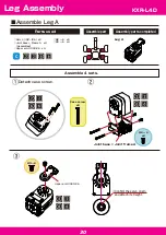
M2.6 ー 10
Horn B
Joint base
Bottom arm
3300-26
Joint Nut
M2 ー 4
x4
①
②
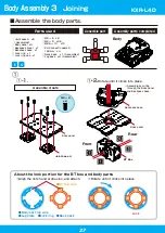
Parts combination
◯Bottom arm 3300-26 x4
◯Joint base x5
◯Joint Nut x5
◯Joint frame B-a x1
◯Joint frame B-b x1
◯Cable guide X x4
◯Joint base + Frame B x4
(Assembled)
◯Horn B x5
◯M2 ー 4 x20
◯M2 ー 6 x14
◯M2.6 ー 10 x10
◯M3 ー 8 x5
◯2.6 ー 4 x4
◯ZH-ZH Connection
Cable 2 200mm
x1
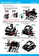
Attach 4 places in the same way.
Attach 4 places in the same way.
Attach in the direction indicated below.
Front
Front-facing
Rear-facing
Rear-facing
Front-facing
Rear
M3 ー 8
B
C
D
A
■
Atach the legs and head to the body.
Assemble part
Assembly parts completed
Parts used
Align with the servo
origin mark.
Points on Attaching to Upper Shaft
A
When the origin deviates with the
diagram position, lightly insert the
arm and rotate to adjust the position.
Attach it straight toward the A line.
Parts Combination 1
Legs and Head
KXR-L4D


