25
UAB KOMFOVENT we reserve the right to make changes without prior notice
DOMEKT_C8_21-01
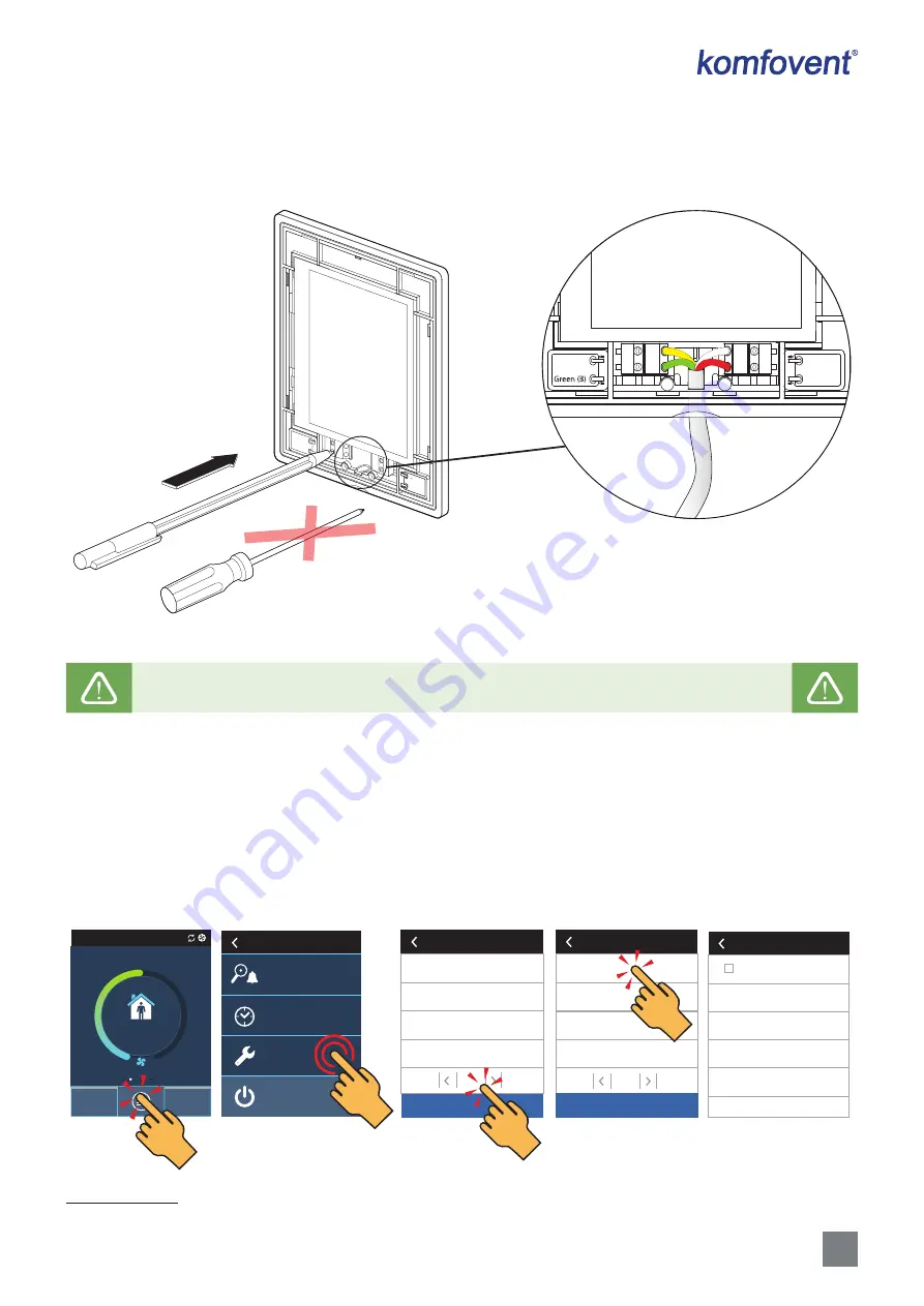
It is advisable to run the control panel cable in such a way that it does not go near the power supply wires or high volta-
ge electrical equipment (electrical inlet cabinets, electric water heating boiler, air conditioning unit, etc.). The cable can be
passed through the holes in the back or bottom of the control panel (follow the installation instructions supplied with the
control panel). The wire to C8 controller board is connected to a dedicated slot (RJ9 connector; see Fig. 10) or to the terminals
for external connections.
Yellow (A)
( ) White
(+) Red
Yellow (A
)
(+) Red
Green (B)
( ) White
Fig. 15.
Cable connection to the control panel
Do not use sharp tools (e.g. screwdriver) to press on the control panel’s contacts. Pencil or ballpoint pen
is best for this.
4.4. Connecting the unit to an internal computer network or the Internet
The unit can be controlled not only by the control panel, but also by computer or smart phone. In such cases, the air
handling unit must be connected to an local computer network or to the Internet. The unit is controlled by a computer using
a web browser, or a smartphone with a Komfovent Home or Komfovent Control app. The air handling unit is connected to
the computer network with a CAT5 type cable (RJ45 connector; see Fig. 10). The total cable length between the unit and the
network router must not exceed 100 m.
By default, the IP address of the air handling unit is 192.168.0.60, but it can be changed (if necessary) according to the
local network parameters. The IP address can be found and changed on the control panel
1
.
16:30
NORMAL
ECO
AUTO
TURN OFF
Settings
Scheduling
Overview
Menu
5 s
DHCP
IP address
192.168.0.60
Gateway
192.168.0.1
BACnet ID
60
Subnet mask
255.255.255.0
Connectivity
Temperature control
Air quality control
Control sequence
Fire dampers
Advanced settings
1
/ 2
Reset settings
Clean filters calibration
Komfovent Control
Advanced settings
2
/ 2
Connectivity
Reset settings
Fig. 16.
View and change the IP address of the AHU on the control panel
1
Only on the C6.1 panel (see Fig. 19).


