


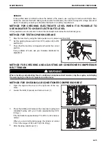

1.
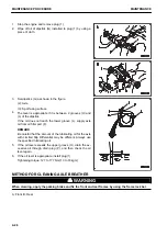
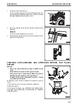
Start the engine and set the engine speed to approximate-
ly 1500 rpm.
2.
Press fan switch (1) and set the air flow to “Hi”.
3.
Press temperature adjustment switch (2) and set the tem-
perature to 18 °C.
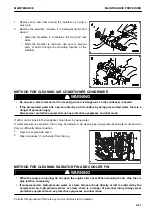
4.
Fully open the doors and windows.
5.
Press air conditioner switch (3) to turn the air conditioner
switch ON.
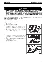
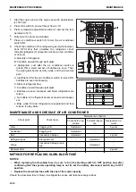
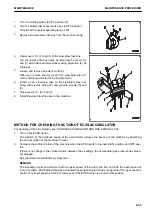
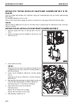
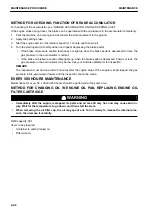
6.
Check the condition of the refrigerant gas (Hydrofluorocar-
bons HFC-134a) that circulates the refrigerant circuit,
through sight glass (5) (inspection window) of air condition-
er hose (4).
A: Quantity of refrigerant
B: Condition viewed through sight glass
a: Appropriate: Just after the air conditioner switch is
turned ON, a small number of bubbles are seen. Then,
the sight glass becomes milky white, and then becomes
pale.
b: Insufficient: After the air conditioner switch is turned ON,
bubbles are seen continuously.
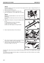
X: State of refrigerant flow
Y: Condition viewed through sight glass
x: Bubbles are seen: Gaseous and liquid refrigerants are
mixed.
y: No bubble: All refrigerant becomes liquid and transpar-
ent.
z: Milky white: Oil and refrigerant are separated and their
mixture is milky white.
MAINTENANCE AND SCHEDULE OF AIR CONDITIONER
Check point
Check items
Maintenance schedule
Check before op-
eration
6 months inspec-
tion
Replacement in-
terval
Filter
Clogging, dirt
Implement
-
2 years
Condenser
Clogging, dirt
Implement
-
-
Belt
Looseness, damage
Implement
-
2 years
Refrigerant gas
Charge amount
-
Implement
-
Piping
Looseness, damage, leak-
age
-
Implement
-
Receiver drier
-
-
-
2 years
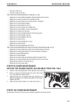
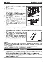
METHOD FOR REPLACING SLOW-BLOW FUSE
NOTICE
• When replacing the slow-blow fuse, be sure to turn the starting switch to OFF position and, after
confirming that the system operating lamp is not lit, set the battery disconnect switch key to OFF
position.
• Replace the slow blow fuse with the one of the same capacity.
Should the slow-blow fuse is blown, investigate the cause and take necessary actions.
MAINTENANCE PROCEDURE
MAINTENANCE
4-34
Summary of Contents for WA480-8
Page 2: ......
Page 19: ...Distributor name Address Phone Fax Service personnel FOREWORD PRODUCT INFORMATION 1 17...
Page 29: ...LOCATION OF SAFETY LABELS SAFETY SAFETY LABELS 2 3...
Page 159: ...SWITCHES 1 ECSS switch 2 Front working lamp switch OPERATION EXPLANATION OF COMPONENTS 3 91...
Page 302: ...Securing position Fixing angle A 61 B 53 C 33 D 38 TRANSPORTATION OPERATION 3 234...
Page 324: ......
Page 397: ...Viewed from the rear side of the machine MAINTENANCE MAINTENANCE PROCEDURE 4 73...
Page 402: ......
Page 403: ...SPECIFICATIONS 5 1...
Page 406: ......
Page 422: ......
Page 423: ...REPLACEMENT PARTS 7 1...
Page 439: ......


