


3.
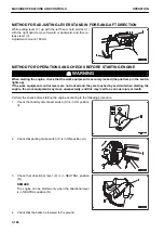
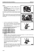
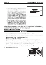
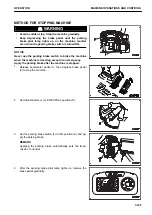
When the engine starts, release the starting switch key (1).
The key returns automatically to ON position (B).
When the engine is started, white smoke may come out of the exhaust pipe. It is fine water particles which are
produced from moisture or water vapor and which seem white, thus it does not indicate an abnormality.
The smell of the exhaust gas is different from that of the conventional diesel machine because of the exhaust
gas filtering function.
START IN COLD WEATHER
k
k
WARNING
• Start the engine only while sitting down in the operator's seat.
• Do not attempt to start the engine by short-circuiting the engine starting circuit.
Doing so may cause a fire or serious personal injury or death.
• Check that there are no people or obstacles in the surrounding area, then sound the horn and start
the engine.
• Exhaust gas is toxic.
When starting the engine in confined spaces, be particularly careful to ensure good ventilation.
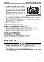
NOTICE
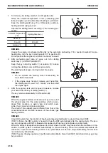
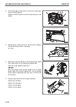
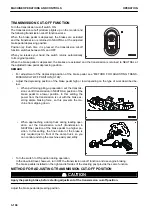
• Do not accelerate the engine abruptly until it is
warmed up.
• This machine is equipped with the automatic warm-up
function to heat the coolant more quickly and the tur-
bo protect function to protect the turbocharger.
In cold weather startup, the engine speed may not
change for several seconds immediately after the
startup even if accelerator pedal (3) is depressed.
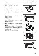
When the engine is started after left at temperature of approxi-
mately -20 °C for more than a half day, it takes time to attain
perfect combustion.
Operate the starting switch according to the following proce-
dure.
OPERATION
MACHINE OPERATIONS AND CONTROLS
3-183
Summary of Contents for WA480-8
Page 2: ......
Page 19: ...Distributor name Address Phone Fax Service personnel FOREWORD PRODUCT INFORMATION 1 17...
Page 29: ...LOCATION OF SAFETY LABELS SAFETY SAFETY LABELS 2 3...
Page 159: ...SWITCHES 1 ECSS switch 2 Front working lamp switch OPERATION EXPLANATION OF COMPONENTS 3 91...
Page 302: ...Securing position Fixing angle A 61 B 53 C 33 D 38 TRANSPORTATION OPERATION 3 234...
Page 324: ......
Page 397: ...Viewed from the rear side of the machine MAINTENANCE MAINTENANCE PROCEDURE 4 73...
Page 402: ......
Page 403: ...SPECIFICATIONS 5 1...
Page 406: ......
Page 422: ......
Page 423: ...REPLACEMENT PARTS 7 1...
Page 439: ......


