background image

TROUBLESHOOTING

145

3.15 TROUBLESHOOTING

3.15.1 HOW TO REMOVE THE MACHINE

DANGER

q

When removing the machine, use a wire rope suitable
for the weight of the machine to be removed.

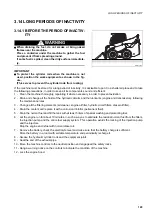
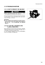
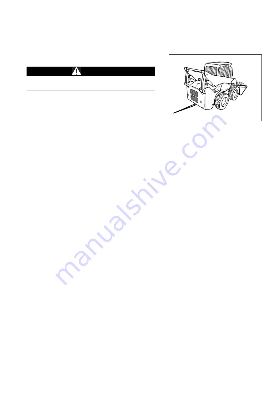
If the machine gets stuck in mud and cannot get out using only
its motive power, or in case of breakdown, use a wire rope as
shown in the figure on the right. 

IMPORTANT

q

In case of failure of the hydraulic circuit, before recover-
ing the machine release the negative brake installed on
the rear axle ( "4.8.1.d RELEASING THE PARKING
BRAKE").

3.15.2 IF THE FUEL HAS BEEN COM-

PLETELY DEPLETED

Before starting the engine when the fuel has been completely
depleted and therefore air has entered the fuel supply circuit, it
is necessary to bleed the fuel supply circuit.
For the necessary operations, see "4.8.8 MAINTENANCE
EVERY 500 HOURS OF OPERATION".

RWA37570

Summary of Contents for SK820-5 turbo

Page 1: ...perators and maintenance personnel must read this manual before operating or maintaining this machine This manual should be kept inside the cab for reference and periodically reviewed by all personnel...

Page 2: ......

Page 3: ...at have been carried out are important to have a clear prospect of the situation and to know exactly what has been done and what has to be done after the next maintenance interval Therefore it is advi...

Page 4: ...erate injury It may also be used to alert against unsafe practices Other signal words In addition to the above the following signal words are used to indicate precautions that should be followed to pr...

Page 5: ...all only authorized additional equipment see 6 1 4 CHARACTERISTICS OF THE OPTIONAL EQUIP MENT OF THE MACHINE VERSION WITH HIGH FLOW AND SUPER FLOW HYDRAULIC SYSTEM WARNING q Travel on roads is allowed...

Page 6: ...ments on the machine and the hydraulic couplings necessary for the operation of the equipment are grouped in the final section of this manual Komatsu MACHINES are constructed exclusively for the handl...

Page 7: ...first 50 hours of use carry out the following operations in addition to those to be performed every 50 hours 1 Check the gearing chain tension 2 Check the wheel nut tightening q After the first 250 h...

Page 8: ...tsu MACHINES described in this manual are provi ded with the CE mark which certifies that they are in com pliance with the CE harmonized standards The plate with the mark is applied on to the inner wa...

Page 9: ...SERIAL NUMBER The serial number of the travel reduction gear is stamped on the plate positioned on the hydraulic motor cover 1 4 5 CAB SERIAL NUMBER The cab serial number is stamped on the plate posit...

Page 10: ...TIFICATION 8 1 4 7 SERIAL NUMBERS AND DEALER S ADDRESS Machine N Model Engine N Dealer Address Tel Person to contact NOTES Excavator if installed N Travel reduction gear N Cab N Product identification...

Page 11: ...1 4 VIBRATIONS TO WHICH THE OPERATOR IS SUBJECTED 23 2 2 GENERAL PRECAUTIONS 24 2 2 1 GENERAL SAFETY RULES 24 2 2 2 SAFETY DEVICES AND GUARDS 24 2 2 3 CLOTHING AND PERSONAL PROTECTION ITEMS 24 2 2 4 U...

Page 12: ...NING PLATES 43 2 8 2 TOOLS 43 2 8 3 PERSONNEL 44 2 8 4 EQUIPMENT 44 2 8 5 WORKING UNDER THE MACHINE 44 2 8 6 KEEPING THE MACHINE CLEAN 44 2 8 7 USE OF THE ENGINE DURING MAINTENANCE 45 2 8 8 PERIODICAL...

Page 13: ...SEAT 104 3 5 6 SAFETY BELT 105 3 5 7 EMERGENCY EXIT 105 3 5 8 TECHNICAL DOCUMENTATION CASE 106 3 5 9 FIRE EXTINGUISHER 106 3 5 10 FIRST AID KIT 106 3 6 USE OF THE MACHINE 107 3 6 1 CHECKS BEFORE START...

Page 14: ...NG THE BUCKET OR THE EQUIPMENT WITH STANDARD RAPID COUPLING 135 3 13 6 1 RELEASING THE BUCKET 136 3 13 6 2 COUPLING THE BUCKET 136 3 13 7 CHANGING THE BUCKET OR THE EQUIPMENT WITH OPTIONAL RAPID COUPL...

Page 15: ...4 8 1 e CHECKING THE BATTERY CHARGE LEVEL 177 4 8 2 CHECKS BEFORE STARTING 178 4 8 2 a VARIOUS CHECKS 178 4 8 2 b CHECKING THE COOLANT LEVEL 178 4 8 2 c CHECKING THE FUEL LEVEL 179 4 8 2 d CHECKING T...

Page 16: ...ARACTERISTICS 210 AUTHORIZED OPTIONAL EQUIPMENT 6 1 AUTHORIZED OPTIONAL EQUIPMENT 214 6 1 1 PRECAUTIONS REGARDING SAFETY 214 6 1 2 PRECAUTIONS REGARDING THE INSTALLATION OF EQUIPMENT 215 6 1 3 CHARACT...

Page 17: ...SAFETY AND ACCIDENT PREVENTION 15...

Page 18: ...ution made of water and detergent Do not use fuel petrol or solvents q If the plates are damaged ask for new ones to Komatsu or to your Komatsu Dealer q In case of replacement of a component provided...

Page 19: ...SAFETY NOISE AND VIBRATION PLATES 17 RWA00010 RWA37020...

Page 20: ...SAFETY NOISE AND VIBRATION PLATES 18 2 1 1 2 SAFETY PLATES FOR MACHINES WITH EXCAVATOR RWA37030 RWA00030 RWA00020...

Page 21: ...SAFETY NOISE AND VIBRATION PLATES 19 RWA37040 RWA00010 RWA00020...

Page 22: ...description illustrates what they look like and their respective meanings DANGER IN THE WORK AREA Only for machines with excavator q Do not approach or stand within the equipment operating ra dius wh...

Page 23: ...VIBRATION PLATES 21 BIOLOGICAL HYDRAULIC OIL TOPPING UP REFUELLING ENGINE LUBRICATING OIL FILTER FUEL FILTER ENGINE AIR SUCTION FILTER ENGINE COOLANT RWA34380 BIO OIL D RWA00040 RWA00080 D RWA00060 R...

Page 24: ...D VIBRATION PLATES 22 ENGINE COOLANT PRESSURE HYDRAULIC OIL LEVEL HYDRAULIC OIL FILTER ELECTRIC OUTLET ANCHORAGE POINT EMERGENCY EXIT LIFTING POINT RWA00110 RWA00100 RWA00070 12 V RWA00120 RWA00200 RW...

Page 25: ...o on the new part NOISE OUTSIDE THE CAB q This value indicates the noise level outside the machine and refers to the noise perceived by the persons who are in the vicinity of the work area NOISE INSID...

Page 26: ...e the safety devices and always keep them in good operating conditions q Improper use of the safety devices may lead to serious injuries or even death 2 2 3 CLOTHING AND PERSONAL PRO TECTION ITEMS q D...

Page 27: ...hat the machine is in a safe position see 2 4 11 PARKING THE MACHINE q Before leaving the operator s seat carry out the following operations in the sequence indicated below 1 Rest the equipment on the...

Page 28: ...s if they are dirty with oil or grease Carefully clean the cab floor if it is dirty with oil grease mud or rubble 2 2 7 CHECKING THE REAR VIEW MIR RORS if installed q Make sure that the rear view mirr...

Page 29: ...up tighten the safety caps of the fuel and oil tanks securely q Do not fill the tank completely in order to leave room for the fuel to expand q In case some fuel is spilled wipe it up immediately 2 2...

Page 30: ...ssible 4 Even if the cab provides suitable protection use an ap proved and homologated respirator 5 The powder gathered during the cleaning operations must be dampened and put in a sealed and marked c...

Page 31: ...HE CAB STRUCTURE q If the cab is inadvertently hit or the machine overturns during work the cab may be damaged with consequent reduction of its stiffness and of the safety that must be guaranteed to t...

Page 32: ...d of the opera tions Be careful not to sever or damage any of these lines q Check the depth and flow of water before operating in water or on river banks 2 3 2 FIRE PREVENTION q Carefully remove all w...

Page 33: ...any faulty bulbs with new ones making sure that their power is correct 2 3 6 CLEANING THE WINDOWS AND THE REAR VIEW MIRRORS CHECKING THE WINDSHIELD WIPER BLADES if installed q Remove any trace of dir...

Page 34: ...e persons in the vicinity q Start the engine only when seated with fastened safety belt q Do not allow anyone to get on the machine 2 4 2 RULES TO BE FOLLOWED WHEN TRAVELLING ON ROADS q The machines h...

Page 35: ...g in areas that may be hazardous or where vi sibility is poor designate a person to direct the movements of the machine and the traffic on the work site q Make sure that no unauthorized person is stan...

Page 36: ...acle keep the equi pment as close to the ground as possible and travel at low speed Never move on obstacles that may incline the machine con siderably over 10 q If one of the two wheels goes over an o...

Page 37: ...control of the machine and cause serious damage and even death q Do not move on slopes with inclination exceeding 15 since the machine may overturn q When the fuel level indicator reaches the red rese...

Page 38: ...rst in case of electrocution 5 Keep the phone number of the electricity company and of the nearest first aid station at hand q If the work equipment accidentally gets entangled in the cables the opera...

Page 39: ...isible the refore proceed with care when clearing the snow 2 4 9 PREVENTING DAMAGE CAUSED BY THE WORK EQUIPMENT q When working in tunnels galleries under electric cables or other ducts air telephone l...

Page 40: ...rest the work equipment on the ground if it is neces sary to park with raised arms make sure that the safety locks are engaged see 3 1 SAFETY LOCKS q Always lock the equipment and travel control by sh...

Page 41: ...he same length q Position the ramps with a maximum inclination of 15 q Make sure that the ramp surface is clean and there is no tra ce of grease oil soil and ice remove any dirt from the whe els befor...

Page 42: ...ted with small sparks or naked flames q Before working with batteries stop the engine and remove the ignition key q Avoid short circuiting the battery terminals through acciden tal contact with metal...

Page 43: ...ing brake of the travel hydraulic motors see 4 8 1 d RELEASING THE PARKING BRAKE q Incorrect manoeuvres may result in serious injuries or even death q To move the machine use properly dimensioned stee...

Page 44: ...paragraph 3 15 1 HOW TO REMOVE THE MACHI NE CAUTION q The maximum pulling force for the emergency recovery is the following F 2600 kg q Use cables having the same length and pull continuou sly withou...

Page 45: ...q To avoid these risks always attach warning plates to the control levers and to the ignition key before performing any maintenance operation if necessary attach additional war ning tags also around t...

Page 46: ...hine q Always lock the machine wheels securely q Do not work under the machine if this is not sufficiently sup ported 2 8 6 KEEPING THE MACHINE CLEAN q Spilled oil or grease scattered tools or broken...

Page 47: ...ystem fuel delivery and return pipes Hydraulic system main delivery pipes of the hydraulic pump q Even if they seem to be in good conditions these components must be periodically changed with new ones...

Page 48: ...elling hold the fuel gun firmly and keep it constan tly in contact with the filler until you have finished in order to avoid sparks due to static electricity q Do not fill the tank completely in order...

Page 49: ...of the operation reconnect first the positive cable and then the negative cable q If electrical welding operations are to be carried out on the machine it is necessary to disconnect the battery and a...

Page 50: ...d the resulting jets are extremely dangerous since they can perforate the skin and penetrate in the blood circulation or injure the eyes For this reason always wear goggles and thick gloves du ring th...

Page 51: ...mful substances such as oil fuel solvents used filters and batteries 2 8 20 PRECAUTIONS TO BE TAKEN WHEN INFLATING THE TYRES q Always bear in mind that tyres can burst while being inflated causing ser...

Page 52: ...n be used only in the hydraulic system it cannot be used for the endothermic engine the transmissions the braking system etc q Before introducing the synthetic biodegradable oil in the hydraulic syste...

Page 53: ...THE MACHINE AND ITS OPERATIONS 51...

Page 54: ...keep the equipment at a given distance from the ground lower the loader arm completely install the antirotation lock of the front equipment and finally lock the equipment control by shifting the safe...

Page 55: ...ty bars see 3 3 5 pos 1 SA FETY BARS q The retainer 5 locks the optional equipment control pedal in the neutral position q The other applications of the safety locks concern exclusive ly the use of th...

Page 56: ...ipment control by shifting the safety device lever to the lock position The excavator safety locks must be used for travelling on roads and applied by proceeding as follows q After folding the bucket...

Page 57: ...SAFETY LOCKS 55 q If the machine is equipped with rear stabilizers raise the supports completely and engage the relevant safety chainsza 5 RWAA4140 1 4 RWAA4170 RWAA4160 3 RWAA4150 2 RWA37420 5...

Page 58: ...nd lock the equipment control by shifting the safety device lever to the lock position q If the machine is equipped with asphalt cutter besides ap plying the antirotation lock already described for th...

Page 59: ...GENERAL VIEWS 57 3 2 GENERAL VIEWS 3 2 1 FRONT GENERAL VIEW 1 Bucket 4 Frame 2 Bucket cylinder 5 Arm 3 Wheels 6 Cab RWA37430 1 2 3 4 5 2 6...

Page 60: ...GENERAL VIEWS 58 3 2 2 REAR GENERAL VIEW 1 Rear panel 3 Lifting cylinder 2 Engine hood 4 Exhaust silencer RWA37440 3 1 2 4...

Page 61: ...loader arm control 3 Right servo control lever ISO PATTERN loader arm and bucket control OPTION PATTERN right wheel travel and bucket con trol 4 Auxiliary hydraulic kit control pedal if installed 5 Fo...

Page 62: ...GENERAL VIEWS 60 10 Left console switches 11 Right console switches RWAA9720 11 RWAA11260 10...

Page 63: ...n for one hour independ ently of its speed When the engine is running the led A positioned under the instrument flashes for the count of the seconds The hour meter keeps functioning even if the machin...

Page 64: ...he normal temperature green range When the indicator reaches the overheating red range the acoustic alarm sounds too If this inconvenience occurs repeatedly try to find out the cause see TROUBLESHOOTI...

Page 65: ...rrectly NOTE q If the warning light remains off when the ignition key is turned to position I this means that the alternator is faulty or broken 1 Generator warning light 7 Speed increase warning ligh...

Page 66: ...ctivates the acoustic alarm with engine at rest when the starting circuit is energized and goes out as soon as the engine lubrication circuit is pressu rized If this warning light remains on or comes...

Page 67: ...comes on when the high speed is selected see 3 3 3 pos 13 SPEED INCREASE BUTTON 8 FLOATING DEVICE WARNING LIGHT It comes on when the floating device is connected see 3 3 3 pos 14 FLOATING DEVICE SWIT...

Page 68: ...the lifting of the work equipment and the machine travel LED on This means that at least one safety function is lacking in this case the solenoid valve is closed and does not permit the lifting and t...

Page 69: ...engine stops and the acoustic alarm sounds Lower the work equipment to the ground see 3 3 5 MACHINE CONTROLS get off the machine and try to locate the trouble B Coil jamming with engine off The acous...

Page 70: ...n if installed 4 Right stabilizer button if installed 5 Working light switch 6 Emergency switch HAZARD 7 Parking light and low beam switch 8 Direction indicator switch 9 Ignition switch 10 Horn 11 Hig...

Page 71: ...n pressed again LED off it releases the parking brake NOTE q The parking brake is automatically engaged whenever the engine stops this is due to the lack of pressure in the hy draulic circuit q The pu...

Page 72: ...his is a button with two temporary positions and the neutral position at its centre Press the button forward or backward to lower or raise the sta bilizer For use see 3 3 5 pos 13 RIGHT STABILIZER CON...

Page 73: ...itch with three positions The neutral position is at the centre Shift the switch lever to the right or to the left to indicate the turn direction 9 IGNITION SWITCH This is a rotary key switch with fou...

Page 74: ...ery of the hydraulic pump to be constantly increased For use see 3 3 5 pos 9 SUPER FLOW HYDRAULIC SY STEM CONTROL 5 LINEE IF INSTALLED 13 SPEED INCREASE BUTTON This button is positioned on the left jo...

Page 75: ...rm sounds when the circuits are energized with the ignition key rotation to position I and is automatical ly disconnected when the engine is started The sounding of the alarm during operation signals...

Page 76: ...ble lever type switch positioned near the ac cumulator to reach it it is necessary to open the engine hood see 3 5 1 ENGINE HOOD The current transmitted by the accumulator to the electric sys tem of t...

Page 77: ...l lever ISO PATTERN travel and steering OPTION PATTERN left wheel travel and loader arm control 3 Right servo control lever ISO PATTERN loader arm and bucket control OPTION PATTERN right wheel travel...

Page 78: ...Floating device control if installed 12 Pattern shifting control if installed 13 Right stabilizer control if installed 14 Left stabilizer control if installed 15 Optionals RWAA10490 11 RWAA11590 12 R...

Page 79: ...ctrical components which may result in malfunc tions of the devices contact your Komatsu Dealer The locking of the servo control safety device is obtained by lifting the bars 1 in vertical position Th...

Page 80: ...ned safety belt before every manoeuvre the operator must take all the precautions indicated 3 6 5 HOW TO MOVE THE MACHINE ISO PATTERN CONTROL SYSTEMERN q Before moving make sure that the parking brake...

Page 81: ...order to obtain maximum precision and maximum efficiency during work q During work the use of the lever must be proportional to the required effort and such as to obtain con stant engine speed q Manoe...

Page 82: ...re to comply with these instructions may lead to serious accidents CAUTION q The self leveling system is operated automatically only when the loader arm is lifted with loaded bucket When the arm is in...

Page 83: ...hydraulic distributors corresponding to each single function are engaged at the same time COMBINED MANOEUVRES N Neutral A Loader arm lowering Bucket folding B Loader arm lowering Bucket opening C Load...

Page 84: ...PMENT CONTROL LOCKING LEVER IF INSTALLED q When travelling on roads make sure that all the safety devices have been engaged q Before leaving the work position lower the equipment to the ground and loc...

Page 85: ...ffort and such as to obtain con stant engine speed q Manoeuvre the lever smoothly without abrupt movements and avoid counterrotations as much as pos sible since these manoeuvres involve untimely wear...

Page 86: ...n travelling on roads make sure that all the safety devices have been engaged q Before leaving the work position lower the equipment to the ground and lock the safety bars vertical position then stop...

Page 87: ...must be proportional to the required effort and such as to obtain con stant engine speed q Manoeuvre the lever smoothly without abrupt movements and avoid counterrotations as much as pos sible since t...

Page 88: ...the equipment and has three fixed positions left neutral ri ght NOTE q To use the pedal 1 lift the safety guard 2 1 Neutral position A HYDRAULIC CIRCUIT CLOSED When the pedal is in this position it is...

Page 89: ...life of both the engine and the machine 6 HAND ACCELERATOR WARNING q The use of the hand accelerator is allowed only under the indicated conditions its use in other conditions may lead to accidents T...

Page 90: ...ravel hydraulic motors see 4 8 1 d RELEASING THE PARKING BRAKE The braking action is obtained by pressing the switch 1 LED ON the release is obtained by pressing the switch again LED OFF IMPORTANT q T...

Page 91: ...only with the engine off and the parking brake applied q To avoid serious injury always operate the equipment while seated in driving position Do not allow anyone to get too close the machine or the e...

Page 92: ...main tenance operations IMPORTANT q When the HIGH FLOW hydraulic button 1 is pressed the flow conveyed to the hydraulic connections positio ned on the left side of the loader arm for the operation of...

Page 93: ...stem it is possible to use equipment that require a high flow hydraulic line left and at the same time a standard flow hydraulic line right with limited oil flow for secondary functions auxiliary hydr...

Page 94: ...advisable to use the normal speed q Do not use the speed increase control when performing steering or counterrotation manoeuvres 11 FLOATING DEVICE CONTROL IF INSTALLED The right joystick grip is pro...

Page 95: ...order to understand the new controls correctly and avoid any damage or fatal injury that may be caused by incorrect movements The pattern change valve 1 is positioned inside the engine hood on the cab...

Page 96: ...ine in any way make sure that the stabilizer feet are completely raised q Before travelling on roads make sure that the safety locks of the stabilizer feet have been applied The left stabilizer is ope...

Page 97: ...the seat STANDARD VERSION RWAA11340 1 2 3 4 5 6 7 8 9 10 11 RWA35800 POSITION COLOUR CAPACITY A INVOLVED CIRCUIT 1 Violet 3 Left parking lights 2 Violet 3 Control panel lights right parking lights 3...

Page 98: ...Rear working lights stop lights 6 Red 10 Power supply of joystick switches floating device pattern shifting 7 Red 10 12 V electric outlet revolving light emergency lights HAZARD 8 Red 10 Power supply...

Page 99: ...container fixed to the right side of the machine frame and can be reached by removing the cover A Other relays are grouped inside the base installed on the pan el B behind the seat and can be reached...

Page 100: ...CRIPTION 5 Relay board A Stop lights B 1 way C 3 way D Momentary high flow E 2 way F Blinking G Detent high flow POSITION DESCRIPTION 6 Parking brake relay POSITION DESCRIPTION 7 Floating device contr...

Page 101: ...opening and closing of the engine hood must be carried out with the bucket resting on the ground OPENING THE HOOD After releasing the lock press the push button 1 and raise the engine hood 2 The maxim...

Page 102: ...r panel can be opened only after opening the engine hood To reach the release lever 2 of the rear panel 1 raise the engine hood see 3 5 1 ENGINE HOOD To open the rear cover 1 lift the lever 2 position...

Page 103: ...q For maintenance or routine operations the cab must be raised carry out this operation according to the proce dure described in section 3 5 3 1 RAISING THE CAB and keep to all the safety precautions...

Page 104: ...overturning protection lock is not engaged q Always tighten the cab fastening screws with the torque indicated in 4 4 2 SPECIFIC DRIVING TORQUES To carry out some maintenance or routine operations it...

Page 105: ...afety split pin 2 of the cab overturning pro tection lock 3 and put it in the appropriate seat 4 2 Lower the cab until it touches the support surface 3 Put back the fastening screws 1 tighten them app...

Page 106: ...f the seat is obtained by operat ing the lever 1 and making the seat slide on the guides once the desired position has been found release the lever and car ry out slight movements in order to make sur...

Page 107: ...ling points and adjustable length 2 it must be well tightened and hold the op erator s hips while leaving the upper part of his body complete ly free 3 5 7 EMERGENCY EXIT The machine is provided with...

Page 108: ...5 9 FIRE EXTINGUISHER CAUTION q The machine s owner must provide for installing and fix ing the fire extinguisher where prescribed q Controllare periodicamente lo stato di carica dell estin tore If th...

Page 109: ...9 the condition of the safety belt 10 the efficiency of the instruments and of the dashboard 11 the condition of the cab windows and the efficiency of the working lights and direction indicators on th...

Page 110: ...of the equipment controls are in the correct position and therefore that the equipment cannot move suddenly and cause accidents The checks concern 1 the locking of the safety bars 2 the hand accelera...

Page 111: ...non compliance with the safety regulations in force q Before starting the engine make sure that there is no one within the operating radius of the machine and sound the horn 3 6 2 1 STARTING WITH WARM...

Page 112: ...ther The preheating is signalled by the warning light positioned on the dashboard 2 Turn the ignition key to position START until the engine starts and for maximum 15 seconds 3 As soon as the engine s...

Page 113: ...d and lock the safety device again by lifting the safety bars see 3 3 5 pos 1 SAFETY BARS 3 6 5 HOW TO MOVE THE MACHINE ISO PATTERN CONTROL SYSTEMERN CAUTION q The procedures to be followed to use any...

Page 114: ...ntrols is released safety bars down and the bucket is folded the equipment control lever must be in neutral position Release the parking brake 1 Pull the hand accelerator lever and set the engine runn...

Page 115: ...s carry out counterrotations only during work CHANGING DIRECTION WHEN THE MACHINE IS NOT MOVING To turn to the LEFT operate the travel lever as indicated be low To move FORWARD push the lever to the l...

Page 116: ...travel lever clockwise by ap proximately 45 HOW TO CARRY OUT A COUNTERROTATION with the machine not moving To turn to the LEFT shift the travel lever to the left with an an gle of 90 with respect to t...

Page 117: ...of the machine and that there are no obstacles in the surrounding area q Be extremely careful when engaging the reverse and make sure that there are no persons working me ans or obstacles in the way q...

Page 118: ...USE OF THE MACHINE 116 2 Operate the joysticks 1 and 2 at the same time shifting them forward or backward to move the machine RWAA13340 1 2 RWA32270 N N...

Page 119: ...otations since they may create dangerous situa tions carry out counterrotations only during work CHANGING DIRECTION WHEN THE MACHINE IS NOT MOVING To turn to the LEFT operate the right joystick by pro...

Page 120: ...the LEFT To turn to the RIGHT shift the right joystick to the NEUTRAL position N the machine will turn to the RIGHT HOW TO CARRY OUT A COUNTERROTATION with the machine not moving To turn to the LEFT p...

Page 121: ...ays check the work area for snow landslips gravel lo ose ground and anything that may suddenly modify the work conditions and the stability of the machine 2 When going up or down a slope with empty bu...

Page 122: ...is sufficiently firm If it is necessary to work with the machine immersed in water make sure that the maximum immersion depth does not exceed 21 cm and in any case that the engine cooling fan does no...

Page 123: ...ne remove the ignition key 1 Park the machine on firm and level ground in a sufficien tly wide space 2 Lower the bucket to the ground 3 Lock the equipment and travel hydraulic control by shifting the...

Page 124: ...le due to the absence of natural ob stacles rotate the bucket forward and thrust its teeth into the ground 2 Lock the equipment and travel hydraulic control by shifting the safety bars to the lock pos...

Page 125: ...been running for a long period and is still hot in this case let the engine idle for about 5 minutes in order to allow it to cool down gradually before stop ping it Before stopping the engine proceed...

Page 126: ...ides q Block the means of transport by positioning wedges be fore and behind each wheel q Make sure that the ramps have the same length are fir mly anchored to the vehicle are parallel to each other a...

Page 127: ...ey 5 Keep the machine in position by putting wedges 2 before and behind the wheels 6 Fix the machine with tie downs or chains 3 in the anchorage points 5 and 6 7 Protect the end of the exhaust pipe 4...

Page 128: ...su Spare Parts Dpt specifying the machine model and se rial number To lift the machine proceed as follows 1 Lower the loader arm to the ground and fold the bucket completely 2 Shift the safety bars to...

Page 129: ...methanol ethanol or propanol based antifreeze 1 If no permanent antifreeze is available use an antifreeze mixture made of ethylene glycol with the addition of anticorrosion and antifoam products Use...

Page 130: ...ormal operating conditions carry out some slow movements either forward and in reverse and operate all the work equipment cylinders slowly more than once These operations serve to warm up and decrease...

Page 131: ...ORTANT q The coolant must be changed only if it is not permanent For the relevant specifications see 4 3 FUEL COOLANT AND LUBRICANTS 2 Make sure that the cooling fan belt is in good conditions 3 Make...

Page 132: ...positioned on the left lever IMPORTANT q The basic illustrations shown are those necessary for a correct use and exploitment of the machine the operator must get to know the controls and the described...

Page 133: ...me time reduce the operator s stress and the straining of the machine components further more this will considerably reduce the time necessary to load the trucks destined to transport the material To...

Page 134: ...he end of stroke 3 Invert the machine motion and dump the bucket on to the truck NOTE q Start loading the truck from the cab side and if the material is sufficiently homogeneous dump from the maximum...

Page 135: ...ard q Go down slopes in reverse with the loader directed forward and lowered bucket q Move changing direction slowly and with the bucket lowered as much as possible q Absolutely avoid reaching the tra...

Page 136: ...digging depth may cause the locking of the movements due to the overloading of the engine and pump and therefore slow down the digging operations 5 To dump material on heaps unload the bucket as soon...

Page 137: ...q Lubricate the levers as required and remove any dirt or debris Lubricate the connection pins as requi red and keep the area around the pins free of dirt and debris Always grease the pins with the b...

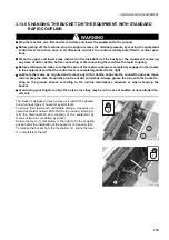
Page 138: ...d move gradually in reverse at the same time rotating the tool holder plate 3 completely forward until releasing it from the upper seat on the bucket 4 3 13 6 2 COUPLING THE BUCKET 1 Make sure that th...

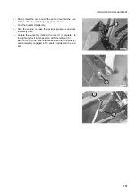
Page 139: ...t completely 5 Stop the engine release the residual pressures and lock the safety bars 6 Couple the bucket by rotating the lever 1 completely to the right and fix it in this position with the retainer...

Page 140: ...E POSITION OF THE LOCKING PINS q Lubricate the levers as required and remove any dirt or debris Lubricate the connection pins as requi red and keep the area around the pins free of dirt and debris Alw...

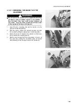
Page 141: ...ng on the ground 1 Lower the arm completely and rest the bucket on to the ground in horizontal position 2 Stop the engine release the residual pressure and lock the controls by lifting the safety bars...

Page 142: ...et 4 until centering its upper lip with the edge of the tool holder cross member 3 Slowly raise the arm and at the same time fold the tool holder until it is completely engaged in its seat 4 Fold the...

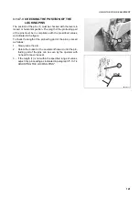
Page 143: ...ibed values as indicated in the figure To check the length of the protruding part of the pins proceed as follows 1 Slowly raise the arm 2 Rotate the bucket or the equipment forward until the pro trudi...

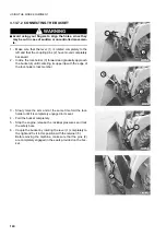
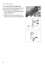
Page 144: ...ition proceeding as indicated below 1 Check the protrusion of the locking pins proceeding as in dicated in paragraph 3 13 7 3 CHECKING THE POSI TION OF THE LOCKING PINS 2 Loosen the lock nut 3 3 Adjus...

Page 145: ...nsmission following the maintenance rules 3 Change all the filtering elements air cleaner engine oil filter hydrulic circuit filters diesel oil filter 4 Drain the coolant and replace it with a corrosi...

Page 146: ...Free the exhaust pipe from the sealing covers 2 Check all the fluid levels engine oil coolant fuel hydraulic circuit and transmission oil 3 Make sure that the battery is charged and install it on the...

Page 147: ...he figure on the right IMPORTANT q In case of failure of the hydraulic circuit before recover ing the machine release the negative brake installed on the rear axle 4 8 1 d RELEASING THE PARKING BRAKE...

Page 148: ...inse the involved part with plenty of water If the acid gets into the eyes immediately rinse with plenty of water and consult a doctor without delay q When working on the battery always wear goggles a...

Page 149: ...used for the starting must have greater capacity or at least the same capacity as the battery of the machine to be started q Make sure that the cables and pliers are neither corroded nor damaged q Ma...

Page 150: ...ulty cables Battery charge insufficient Faulty main fuse Check and repair Charge battery Change Starter pinion engages and then disen gages Battery charge insufficient Charge battery Starter makes eng...

Page 151: ...scale Faulty instrument Change Engine coolant temperature indicator always at the end of left scale Faulty thermostat Faulty instrument Change Change Engine does not start with starter run ning No fu...

Page 152: ...el oil filter and check injection pump Repair or change Set Restore connection shift lever to correct position Set Check oil level and clean exchan ger Repair or change Traction force is insufficient...

Page 153: ...rect Check clogging of diesel oil filter injection pump and valves Set to rated value Oil leakages from engine propeller shaft and or pump Sealing rings faulty Counterpressure in pump casing By pass...

Page 154: ...152 PAGE INTENTIONALLY LEFT BLANK...

Page 155: ...MAINTENANCE 153...

Page 156: ...fety plates applied on to the machine q Instructions for arc welding 1 Turn the ignition key to position 2 Disconnect the battery first the negative pole and then the positive pole 3 Disconnect the al...

Page 157: ...nk with oil of the available brand WARNING q Oils filters coolants and batteries are considered special waste and must be collected and disposed of according to the regulations in force q The combusti...

Page 158: ...f anticorrosion and antifoam products The antifreeze water ratio must be 50 50 antifreeze and 50 water q The use of permanent antifreeze requires only the routine change It is not necessary to wash th...

Page 159: ...ulic circuit is removed after reassembly bleed the circuit by proce eding as follows 1 start the engine and let it idle 2 make all the cylinders perform 4 5 movements stopping them at approx 100 mm fr...

Page 160: ...ng parts q Keep the lubricants at the correct levels excessive or insufficient quantities are to be avoided 4 2 5 PARTS SUBJECT TO WEAR THAT PERIODICALLY NEED CHANGING The parts subject to wear such a...

Page 161: ...sion OIL API CD 39 27 Hydraulic system with biodegrada ble oil SEE 4 3 1 39 27 Final transmis sion case ea OIL API CD 15 5 15 5 Fuel tank DIESEL OIL 50 Engine cooling system PERMANENT COOLANT 9 LUBRIC...

Page 162: ...ssification is used reduce the engine oil change interval by a half q Use Komatsu genuine products whose characteristics have been specifically formulated and approved for use in the engine in the equ...

Page 163: ...endothermic engine the transmissions the braking system etc q Before introducing the synthetic biodegradable oil in the hydraulic system empty the system complete ly disconnecting the cylinders and a...

Page 164: ...5 1 75 2 10 13 17 19 22 0 96 0 1 2 3 0 2 4 6 0 5 7 8 0 8 12 5 1 9 5 1 23 2 45 4 9 77 8 122 13 1 3 0 15 3 2 0 3 6 5 0 6 11 1 17 5 2 13 5 1 5 32 2 3 5 63 6 5 108 11 172 18 16 18 20 22 24 2 2 5 2 5 2 5 3...

Page 165: ...For the lubrication procedures for the single points see 4 7 MAINTENANCE PLAN q The type of lubricant to be used is indicated in the lubricant table see 4 3 FUEL COOLANT AND LUBRI CANTS RWA37580 500 h...

Page 166: ...s immediately in case of failures or anomalies even if the time interval prescribed for their change has not elapsed yet If the pipe clamps show signs of deterioration like deformations or cracks prov...

Page 167: ...dically changed q When changing pipes always change O rings gaskets and analogous components No Components related to safety that periodically need changing Q ty Change interval 1 Fuel pipe Fuel tank...

Page 168: ...regarding the components connected with safety and the components that must be pe riodically changed q When changing pipes always change O rings gaskets and analogous components No Components related...

Page 169: ...ponents related to safety that periodically need changing Q ty Change interval 3 Hydraulic pipe Lifting cylinder 6 Every 2 years or 4000 hours whichever oc curs first 4 Hydraulic pipe Bucket cylinder...

Page 170: ...nents connected with safety and the components that must be pe riodically changed q When changing pipes always change O rings gaskets and analogous components No Components related to safety that peri...

Page 171: ...ponents related to safety that periodically need changing Q ty Change interval 4 Hydraulic pipe Lifting cylinder 6 Every 2 years or 4000 hours whichever oc curs first 5 Hydraulic pipe Bucket cylinder...

Page 172: ...IODICAL CHANGE OF THE COMPONENTS CONNECTED WITH SAFETY 170 OPERATOR S SAFETY No Components related to safety that periodically need changing Q ty Change interval 1 Safety belt 1 Every 4 years RKAB0320...

Page 173: ...NAN CE EVERY 50 HOURS OF OPERATION a CHECKING THE GEARING CHAIN TENSION 185 b CHECKING THE WHEEL NUT DRIVING TORQUE 187 c CHANGING THE HYDRAULIC OIL DRAIN FILTER 194 MAINTENANCE EVERY 50 HOURS OF OPER...

Page 174: ...NG THE FUEL FILTER 192 b CHANGING THE HYDRAULIC OIL DRAIN FILTER 194 c CLEANING THE WATER SEPARATOR 195 d DRAINING THE HYDRAULIC OIL TANK Only for machines filled with synthetic biodegradable oil type...

Page 175: ...aner can be reached after lifting the engine hood see 3 5 1 ENGINE HOOD and opening the rear panel see 3 5 2 REAR PANEL To clean the primary element proceed as follows 1 Remove the couplings 1 and rem...

Page 176: ...incorrect mano euvres that may shorten their life The manoeuvres to be avoided are the following 1 Excessive skidding when loading material 2 Abrupt steering starting and stopping manoeuvres 3 Excess...

Page 177: ...engage the safety lock see 3 1 1 LOADER LOCKS 3 Rotate the lever 1 anticlockwise until only clean fuel flows out of the pipe connected to the drain cock of the tank 4 Rotate the lever clockwise 1 to i...

Page 178: ...pipe 1 that supplies pressure to the tra vel motors 3 Connect the grease nipple 3 to the union 2 4 Using the grease pump provided inject grease until rea ching the minimum pressure required to releas...

Page 179: ...colours according to the table positioned beside the in dicator q Green the charge is correct q Grey the battery needs recharging q White the battery must be changed CAUTION q If it is necessary to w...

Page 180: ...y and precisely 6 soundness of the safety belt 7 soundness and legibility of the warning plates 8 cleanliness of the handles and footboards used to reach the driver s cab cleanliness inside the driver...

Page 181: ...ndicator 1 positioned on the dashboard after turning the ignition key to position While refuelling check the fuel level on the sight gauge 2 The gauge shows only the last litres of fuel that can be co...

Page 182: ...ld engine and the machi ne positioned on level ground The oil level must be checked on the graduated dipstick 1 and must be included between the MIN and MAX marks if the level is near the MIN mark top...

Page 183: ...cuit open the rear panel see 3 5 2 REAR PANEL The oil level must be visible through the gauge 1 positioned on the tank and must be included between the MIN and MAX marks If the level is near the MIN m...

Page 184: ...cock 2 4 Drain the fuel tank as described in paragraph 4 8 1 c DRAINING THE FUEL TANK 5 Bleed the fuel supply circuit as described in paragraph 4 8 8 a CHANGING THE FUEL FILTER IMPORTANT q If the fil...

Page 185: ...and duration of the tyres The pressure must be as indicated in the specifications see 5 1 3 TECHNICAL CHARACTERISTICS While checking the tyre pressure check also the conditions of the tread and sidew...

Page 186: ...BELT TENSION The fan belt can be reached after raising the engine hood see 3 5 1 ENGINE HOOD and the rear panel see 3 5 2 REAR PANEL The check is manual press the belt 1 with your thumb on the indica...

Page 187: ...ving the wheel make sure that the point moves of a distance included between 2 and 6 mm This range determines the correct tension of the chain Repeat this operation also for the opposite wheel REAR CH...

Page 188: ...ng the hub holding plate 1 or 2 mm forwards 5 Fasten at least 3 diametrically opposite nuts 2 of the hub holding plate 6 Install the wheel and check the wheel slack If the wheel slack value is not inc...

Page 189: ...fects the heat exchange adversely q Clean the outside of the radiators whenever the radiator and the heat exchanger are dirtied even if accidentally with oil diesel oil greasy or oily substances q If...

Page 190: ...out on each transmission with the machine at rest on level ground The check is visual and serves to verify that the lubricant rea ches the height of the hole 1 if this is not the case top up using the...

Page 191: ...See 4 3 FUEL COOLANT AND LUBRICANTS NOTE q As a general rule consider that each cylinder is provided with two grease nipples positioned on the couplings and that each pin serving as fulcrum for a mov...

Page 192: ...succession is the following 1 Detach the lower cover 1 after removing the fastening screws 2 Use a 17 mm spanner 2 Extract the oil drain flexible pipe 3 from the lower ope ning 3 Raise the engine hoo...

Page 193: ...or q Oils filters coolants and batteries are considered spe cial waste and must be collected and disposed of ac cording to the anti pollution regulations in force This operation must be carried out on...

Page 194: ...element after work when the engine has cooled down to 40 45 C q When these operations are carried out fuel may be spil led clean the dirty areas immediately in order to pre vent any risk of slipping...

Page 195: ...the ignition key to posi tion for a few seconds and wait at least 2 minutes before starting the engine q If the engine starts without problems and then stops or works irregularly check if there is ai...

Page 196: ...after the first 50 hours of operation and the successive changes eve ry 500 hours The filter is positioned on the hydraulic system drain outlet and blocks the metal particles that come off the various...

Page 197: ...tighten the metal ring 2 and open the cock 1 IMPORTANT q When disassembling the water separator be careful not to lose the red ring contained in the cup q If the filtering element is clogged or damag...

Page 198: ...e present in the equipment by operating the controls more than once Raise the engine hood see 3 5 1 ENGINE HOOD and open the rear panel see 3 5 2 REAR PANEL 1 Slowly loosen the filling cap 1 to releas...

Page 199: ...oil becomes fluid and can be drained easily to gether with the solid particles suspended in it Before changing the oil lift the loader arm and secure it with the safety lock see 3 1 1 LOADER LOCKS 1...

Page 200: ...ng out any maintenance operation q Immediately clean any area dirty with oil q Oils filters coolants and batteries are considered spe cial waste and must be collected and disposed of ac cording to the...

Page 201: ...ion spanner 8 If the oil does not reach the maximum level top up with the prescribed oil see 4 3 FUEL COOLANT AND LU BRICANTS 9 After the check lower the cab screw the filling cap 1 close the rear pan...

Page 202: ...the descaling of the circuit Before changing the coolant lift the loader arm and secure it with the safety lock see 3 1 1 LOADER LOCKS 1 Raise the engine hood see 3 5 1 ENGINE HOOD and open the rear...

Page 203: ...q Oils filters coolants and batteries are considered spe cial waste and must be collected and disposed of ac cording to the anti pollution regulations in force Stop the machine on a firm and level su...

Page 204: ...6 the gasket 7 and the lower plug 2 6 Complete the tank filling operations by proceeding as de scribed in paragraph 4 8 9 b CHANGING THE HYDRAU LIC SYSTEM OIL AND CLEANING THE SUCTION FILTER CAUTION...

Page 205: ...TECHNICAL SPECIFICATIONS 203...

Page 206: ...reases by 200 kg when it is equipped with solid tyres q If the bucket is provided with teeth the machine length increases by 100 mm q With extended bucket the machine length increases by 130 mm OVERAL...

Page 207: ...L DIMENSIONS WITH BUCKET L 1550 AND TYRES 10x16 5 OVERALL DIMENSIONS WITH BUCKET L 1800 AND TYRES 10x16 5 RWA36810 1070 2070 2250 1060 1290 3420 180 1550 1380 210 RWA36830 1070 2070 2250 1060 1290 342...

Page 208: ...weight of the machine increases by 200 kg when it is equipped with solid tyres MACHINE OVERALL DIMENSIONS WITH EXCAVATOR E30 MACHINE OVERALL DIMENSIONS WITH ASPHALT CUTTER RWA36840 1070 2250 2360 2070...

Page 209: ...TECHNICAL DATA 207 OVERALL DIMENSIONS WITH PALLET FORKS OVERALL DIMENSIONS WITH SNOW BLADE RWA36860 1070 2250 1060 1600 3730 180 1670 1380 RWA36870 1070 2250 1060 1340 3470 150 1700 1670 1380...

Page 210: ...208 TECHNICAL DATA OVERALL DIMENSIONS WITH MIXING BUCKET OVERALL DIMENSIONS WITH SWEEPER RWA36880 1070 2250 1060 1400 3530 225 1670 1380 RWA36890 1070 2250 1060 1920 4050 110 1680 1670 1550 80 50 1380...

Page 211: ...TECHNICAL DATA 209 OVERALL DIMENSIONS WITH GRAPPLE FORK RWA36900 1070 2250 1060 1320 3450 180 1670 1460 1380...

Page 212: ...3 0 35 Standard bucket L 1730 capacity SAE m3 0 40 Wide bucket L 1800 capacity SAE m3 0 41 ENGINE Komatsu diesel engine model S4D84E 5KFD Rated power 3000 rpm EEC 80 1269 kW 38 6 Maximum torque 1800 r...

Page 213: ...TECHNICAL DATA 211 SOLID TYRES SIZE MAKE 10x16 5 AIR BOSS...

Page 214: ...212 PAGE INTENTIONALLY LEFT BLANK...

Page 215: ...AUTHORISED OPTIONAL EQUIPMENT 213...

Page 216: ...ure to comply with this recommendation Komatsu declines any responsibility for accidents or dama ge WARNING q When removing or installing any equipment take the following precautions and be careful to...

Page 217: ...reduces the stability of the machine If it is necessary to go up or down a slope be particularly careful since the machine may lose its bal ance and overturn q When installing work equipment with dim...

Page 218: ...x tooth length EQUIPMENT MAX WEIGHT kg MAX DIMENSIONS MAX SAE CAPACITY cu m MAX OPERA TING PRESSURE bar MAX FLOW RATE l min Width mm Height mm Front bucket 200 1800 600 0 422 Multi purpose front bucke...

Page 219: ...x tooth length T Cutting depth EQUIPMENT MAX WEIGHT kg MAX DIMENSIONS MAX SAE CAPACITY cu m MAX OPERA TING PRESSURE bar MAX FLOW RATE l min Width mm Height mm Front bucket 200 1800 600 0 422 Multi pur...

Page 220: ...OR THE EQUIPMENT WITH STANDARD RAPID COUPLING Besides the assembly on the tool holder the hydraulic excavator requires also the fastening to the machine by means of two connection tie rods and the hyd...

Page 221: ...ean any area dirty with oil After the mechanical connection of equipment with indepen dent hydraulic circuit make sure that the auxiliary kit control pedal is in position A flow interrupted and introd...

Page 222: ...CHANGING THE AUTHORIZED EQUIPMENT 220 RWAA11840 D 2 1 RWA36110 1 3 16 UN 1 3 16 UN 1 2 RWAA11830 C 1 2 RWA36090 1 UNS 1 UNS 1 2...

Page 223: ...hen lock the safety bars see 3 3 5 pos 1 SAFETY BARS q Immediately clean any area dirty with oil The machine may be fitted for the application of equipment with separate return circuit directed into t...

Page 224: ...til the rear wheels are partially raised this ma noeuvre stabilizes the machine and avoids any tyre over load see 3 3 5 pos 13 RIGHT STABILIZER CONTROL IF INSTALLED e pos 14 LEFT STABILIZER CON TROL I...

Page 225: ...t may cause the load to move q Use the maximum fork width possible q The forks must always be resting on the plate and be secured in their position by means of the safety pins The pallet forks make it...

Page 226: ...n carry out the first manoeuvres slowly and very carefully in order to understand the new controls correctly and avoid any damage or fatal injury that may be caused by incorrect movements q After chan...

Page 227: ...2 controlling the pattern change valve has two po sitions A Position for the ISO PATTERN CONTROL SYSTEM B Position for the OPTION PATTERN CONTROL SYSTEM RKAB1390 A 2 RKA10390 ISO PATTERN N F N R RKAB...

Page 228: ...desired operating pattern by rotating the lever 2 to position A for the ISO PATTERN or to position B for the OPTION PATTERN 3 Secure the lever in the selected position with the safety screw 3 IMPORTAN...

Page 229: ...n how to use them see 3 3 5 MACHINE CON TROLS 1 Left joystick control lever HAND FOOT CONTROL SYSTEM Left wheel travel 2 Right joystick control lever HAND FOOT CONTROL SYSTEM Right wheel travel and au...

Page 230: ...s make sure that all safety locks are engaged q Before leaving the operator seat stop the engine only after lowering the equipment to the ground and locking the controls safety bars lifted in vertical...

Page 231: ...the engine running at moderate speed in order to obtain maximum precision and maximum productivity during work q During work the use of the levers must be proportional to the effort required and such...

Page 232: ...re leaving the operator seat stop the engine only after lowering the equipment to the ground and locking the controls safety bars lifted in vertical position q Non compliance with these rules may lead...

Page 233: ...loader arm as indicated in the follow ing diagram N Neutral A Loader arm up B Loader arm down IMPORTANT q On machines provided with floating device press the pedal to position B arm down and press the...

Page 234: ...232 The pedal 2 positioned on the operator s right controls the folding and dumping of the bucket as indicated in the follow ing diagram N Neutral A Bucket folding B Bucket dumping 2 RKAB1480 N N A A...

Page 235: ...1 is positioned on the operator s right and controls the movement of the right wheels and the auxiliary hy draulic kit according to the movements indicated on the plate 2 and in the following diagram...

Page 236: ...t allow the optional equipment to be used 2 Positions C and D OPEN HYDRAULIC CIRCUIT These positions are used to control optional equipment with bidirectional oil flow multi purpose bucket drill as ph...

Page 237: ...ch as excavator demolition hammer sweeper etc To hold the lever 1 in coupling position E rotate the lever further to the left NOTE q The lever 1 remains in coupling position E only with pres surised h...

Page 238: ...that there are no persons other equip ment or obstacles in the way q Avoid any travel manoeuvre or change of direction with the accelerator at maximum speed since ma noeuvres carried out in these cond...

Page 239: ...HAND FOOT CONTROL SYSTEM 237 2 Shift the joysticks 1 and 2 forwards or backwards at the same time to move the machine RWAA13340 1 2 RWA32270 N N...

Page 240: ...dangerous situations make counter rotations only during work q Do not use the speed increase function when changing direction or carrying out a counter rotation CHANGING DIRECTION WITH MACHINE AT REST...

Page 241: ...turn to the RIGHT shift the right joystick to the NEUTRAL position N and the machine will turn to the RIGHT HOW TO PERFORM A COUNTER ROTATION with machine at rest To perform a counter rotation to the...

Page 242: ...240 PAGE INTENTIONALLY LEFT BLANK...

Page 243: ......

Page 244: ...2004 KOMATSU UTILITY EUROPE S p A All Rights Reserved Printed in Europe...

Reviews: