


METHOD FOR OPERATIONS AND CHECKS BEFORE STARTING ENGINE
k
k
WARNING
• On starting the engine, check that the safety locking
lever is in the LOCK position. If the lock lever is not
locked securely and the control levers or control pedal
are touched when the engine is started, the machine
may move unexpectedly, and this may lead to serious
personal injury or death.
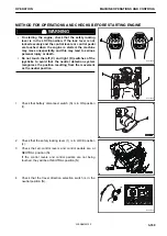
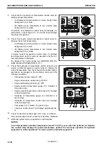
• Do not touch the left (C) and right (D) switches of the
joysticks to avoid that the neutral detection system
recognises the position resulting from the movement
as the neutral position.
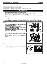
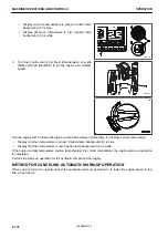
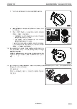
1.
Check that battery disconnect switch (S) is in ON position
(I).
2.
Check that the safety locking lever (1) is in LOCK position
(L).
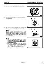
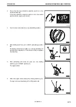
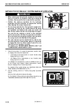
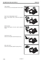
3.
Check that all control levers and control pedals are at
NEUTRAL position (N).
If the control levers and control pedals are not being
touched, they will be at NEUTRAL position (N).
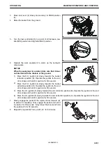
4.
Check that the travel direction selection switch is in the
neutral position (N).
RKA48660
RKA48650
RKA61630
OPERATION
MACHINE OPERATIONS AND CONTROLS
3-169
WENAM00130
Summary of Contents for PW118MR-11
Page 2: ......
Page 9: ...Do not repeatedly handle and lift loads FOREWORD VIBRATION LEVEL 1 7 WENAM00130...
Page 22: ...WENAM00130...
Page 25: ...LOCATION OF SAFETY LABELS RKA64590 SAFETY SAFETY LABELS 2 3 WENAM00130...
Page 72: ...WENAM00130...
Page 74: ...GENERAL VIEW MACHINE EQUIPMENT NAME RKA61930 GENERAL VIEW OPERATION 3 2 WENAM00130...
Page 77: ...CONTROLS AND GAUGES NAMES RKA62690 OPERATION GENERAL VIEW 3 5 WENAM00130...
Page 168: ...SWITCHES RKA63060 EXPLANATION OF COMPONENTS OPERATION 3 96 WENAM00130...
Page 328: ...WENAM00130...
Page 412: ...WENAM00130...
Page 413: ...SPECIFICATIONS 5 1 WENAM00130...
Page 445: ...REPLACEMENT PARTS 7 1 WENAM00130...
Page 461: ......
Page 462: ......