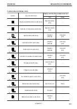


INDICATOR SIGNALLING UNLOCKING OF EMERGENCY ROTATION
The swing lock pilot lamp shows the state of the swing brake
cancel switch.
The pilot lamp display when the swing brake cancel switch is
operated is as follows.
Pilot lamp flashes: Swing brake cancel switch ON
Pilot lamp goes out: Swing brake cancel switch OFF
For information about the swing brake cancelling switch, see
“SWING BRAKE CANCEL SWITCH (3-107)” and “SWITCHES
(3-96)”
AUTO-DECELERATION PILOT LAMP
The auto-deceleration pilot lamp shows the setting of the auto-
deceleration either ON or OFF.
The pilot lamp display when the auto-deceleration switch is op-
erated is as follows.
Pilot lamp lights up: Auto-deceleration ON
Pilot lamp goes out: Auto-deceleration OFF
TURRET ALIGNMENT WARNING LIGHT
The travel alignment caution lamp shows the alignment status of the turret.
The caution lamp functions as indicated below.
Warning light on: The upper turret and lower body are aligned.
Warning light off: The upper turret and lower body are not
aligned.
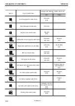
WORKING MODE DISPLAY
The working mode display shows the setting of the working
mode.
The working mode set with the working mode switch is shown
as follows.
“P”: P mode (for heavy-duty operations)
“E”: E mode (for operations with emphasis on fuel consump-
tion)
“L”: L mode (for fine control operations)
“B”: B mode ( for breaker operations) (For machines ready for
installation of attachments)
“ATT/P”: ATT/P mode (for operations of 2-way attachments like crusher, etc.)
“ATT/E”: ATT/E mode (for operations of 2-way attachments like crusher in emphasis of fuel consumption)
TRAVEL SPEED PILOT LAMP
The travel speed pilot lamp shows the travel speed that has been set.
OPERATION
EXPLANATION OF COMPONENTS
3-35
WENAM00130
Summary of Contents for PW118MR-11
Page 2: ......
Page 9: ...Do not repeatedly handle and lift loads FOREWORD VIBRATION LEVEL 1 7 WENAM00130...
Page 22: ...WENAM00130...
Page 25: ...LOCATION OF SAFETY LABELS RKA64590 SAFETY SAFETY LABELS 2 3 WENAM00130...
Page 72: ...WENAM00130...
Page 74: ...GENERAL VIEW MACHINE EQUIPMENT NAME RKA61930 GENERAL VIEW OPERATION 3 2 WENAM00130...
Page 77: ...CONTROLS AND GAUGES NAMES RKA62690 OPERATION GENERAL VIEW 3 5 WENAM00130...
Page 168: ...SWITCHES RKA63060 EXPLANATION OF COMPONENTS OPERATION 3 96 WENAM00130...
Page 328: ...WENAM00130...
Page 412: ...WENAM00130...
Page 413: ...SPECIFICATIONS 5 1 WENAM00130...
Page 445: ...REPLACEMENT PARTS 7 1 WENAM00130...
Page 461: ......
Page 462: ......