


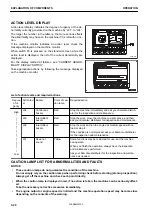


AXLE LOCKING SYSTEM CAUTION LAMP
This caution lamp signal faults in the axle lock system.
When faults are present:
The caution lamp turns red, the alarm buzzer operates intermit-
tently and the action level “L03” is displayed.
Stop the operation and move the machine to a safe place, and
then ask your Komatsu distributor for inspection and mainte-
nance.
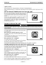
GEAR ENGAGEMENT CAUTION LAMP
The gear not engaged alarm indicator indicates that the gear is
not engaged correctly.
When abnormal:
The caution lamp lights up in red and the alarm buzzer sounds
continuously.
Lightly press the drive pedal to allow the gear to be engaged
correctly and keep it pressed until the light goes off.
HYDRAULIC QUICK COUPLER SYSTEM CAUTION LAMP
This indicator signals that there are faults in the hydraulic quick
coupling system.
When there is an abnormality:
The caution lamp lights up in red and the alarm buzzer sounds
intermittently and indicates action level “L03”.
Stop the machine immediately and ask your Komatsu distribu-
tor for inspection.
REMARK
This indicator comes on with a red light also when the quick
coupler locking/unlocking operations are carried out. In this
case the warning indicator emits a continuous sound and the
intervention level is not displayed on the monitor. This is there-
fore not an alarm for an anomaly or fault. For details, see “OP-
ERATION OF QUICK COUPLER (6-5)”
STEERING SYSTEM CAUTION LAMP
This indicator signals faults in the steering system.
When there is an abnormality:
The caution lamp lights up in red and indicates action level
“L03”.
Stop the machine and ask your Komatsu distributor for inspec-
tion.
RKA47870
RKA51980
RKA48750
RKA48920
OPERATION
EXPLANATION OF COMPONENTS
3-31
WENAM00130
Summary of Contents for PW118MR-11
Page 2: ......
Page 9: ...Do not repeatedly handle and lift loads FOREWORD VIBRATION LEVEL 1 7 WENAM00130...
Page 22: ...WENAM00130...
Page 25: ...LOCATION OF SAFETY LABELS RKA64590 SAFETY SAFETY LABELS 2 3 WENAM00130...
Page 72: ...WENAM00130...
Page 74: ...GENERAL VIEW MACHINE EQUIPMENT NAME RKA61930 GENERAL VIEW OPERATION 3 2 WENAM00130...
Page 77: ...CONTROLS AND GAUGES NAMES RKA62690 OPERATION GENERAL VIEW 3 5 WENAM00130...
Page 168: ...SWITCHES RKA63060 EXPLANATION OF COMPONENTS OPERATION 3 96 WENAM00130...
Page 328: ...WENAM00130...
Page 412: ...WENAM00130...
Page 413: ...SPECIFICATIONS 5 1 WENAM00130...
Page 445: ...REPLACEMENT PARTS 7 1 WENAM00130...
Page 461: ......
Page 462: ......