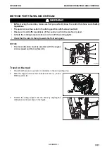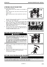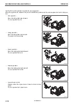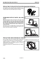
4.
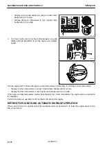
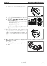
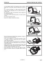
Position the swing support and the chassis by aligning the
collimation marks as shown in the figure.
5.
Position the arm by aligning the decal with the reference
as shown in the figure.
6.
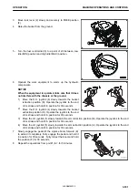
Lift the blade or outriggers. If the machine is equipped with
outriggers, fasten them with safety cables.
7.
Secure a metal cable to the pins of the bucket as shown in
the figure
8.
Insert the boom rotation pedal stop (2).
9.
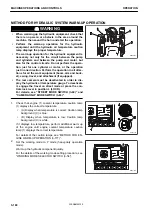
Check that the outriggers or blade are raised and that the
attachment is raised from the ground by at least 40-50 cm.
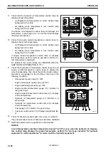
10. Check that the work brake is disengaged. For details, see
11. Check that the control levers are in the neutral position.
12. Check that the axle lock is deactivated. For details of the
caution lamps, see “AXLE LOCK SWITCH (3-102)”.
13. Check the alignment of the turret and align it if necessary.
For details of the caution lamps, see “TURRET ALIGN-
MENT WARNING LIGHT (3-50)”.
RKA63890
RKA54110
MACHINE OPERATIONS AND CONTROLS
OPERATION
3-192
WENAM00130
Summary of Contents for PW118MR-11
Page 2: ......
Page 9: ...Do not repeatedly handle and lift loads FOREWORD VIBRATION LEVEL 1 7 WENAM00130...
Page 22: ...WENAM00130...
Page 25: ...LOCATION OF SAFETY LABELS RKA64590 SAFETY SAFETY LABELS 2 3 WENAM00130...
Page 72: ...WENAM00130...
Page 74: ...GENERAL VIEW MACHINE EQUIPMENT NAME RKA61930 GENERAL VIEW OPERATION 3 2 WENAM00130...
Page 77: ...CONTROLS AND GAUGES NAMES RKA62690 OPERATION GENERAL VIEW 3 5 WENAM00130...
Page 168: ...SWITCHES RKA63060 EXPLANATION OF COMPONENTS OPERATION 3 96 WENAM00130...
Page 328: ...WENAM00130...
Page 412: ...WENAM00130...
Page 413: ...SPECIFICATIONS 5 1 WENAM00130...
Page 445: ...REPLACEMENT PARTS 7 1 WENAM00130...
Page 461: ......
Page 462: ......

