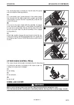


REMARK
• Spare fuses are installed in the back of the fuse holder lid
at the rear left of the operator's seat.
• If the spare fuses are used, replace the missing fuses im-
mediately.
• One spare fuse is supplied for each type 5 A, 10 A, 20 A,
25 A, and 30 A.
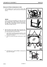
FUSIBLE LINK
NOTICE
Before replacing a fusible link, be sure to turn the starting
switch to OFF position, then turn the battery disconnect
switch key to OFF position.
If the following phenomena occur, fusible links are suspected of
disconnection. Open the rear lefthand hatch, check the power
fuse and replace it if necessary.
• If the engine starter motor does not function even if the key
in the starting switch is turned to the START position, the
power fuse (1) may have blown.
• If the battery runs flat, the power fuse (2) may have blown.
• If the engine does not start easily in cold weather even if the starting switch is set to HEAT (preheat) posi-
tion, fusible link (3) may be broken.
REMARK
A power fuse is a high capacity fuse installed in the power section of the electrical circuit.
It protects the electrical components and wiring from burning, as guaranteed by a standard fuse.
Item
Capacity
Name of circuit
Connector No.
Part No.
(1)
65 A
Standard power supply
F02
22U-06-11270
(2)
65 A
DC power supply
F03
22U-06-11270
(3)
120 A
Preheating
F06
421-06-22830
CONTROL UNITS
NOTICE
• Do not let water, mud, or beverage spill on the control-
ler. This will cause failures.
• If any problem occurs in the controller, do not repair it
by yourself. Contact your Komatsu distributor for re-
pair.
(1) KomVision control unit
(2) Komtrax control unit
(3) Pump control unit
(4) Machine control unit
(5) Engine control unit
RKA65010
OPERATION
EXPLANATION OF COMPONENTS
3-129
WENAM00130
Summary of Contents for PW118MR-11
Page 2: ......
Page 9: ...Do not repeatedly handle and lift loads FOREWORD VIBRATION LEVEL 1 7 WENAM00130...
Page 22: ...WENAM00130...
Page 25: ...LOCATION OF SAFETY LABELS RKA64590 SAFETY SAFETY LABELS 2 3 WENAM00130...
Page 72: ...WENAM00130...
Page 74: ...GENERAL VIEW MACHINE EQUIPMENT NAME RKA61930 GENERAL VIEW OPERATION 3 2 WENAM00130...
Page 77: ...CONTROLS AND GAUGES NAMES RKA62690 OPERATION GENERAL VIEW 3 5 WENAM00130...
Page 168: ...SWITCHES RKA63060 EXPLANATION OF COMPONENTS OPERATION 3 96 WENAM00130...
Page 328: ...WENAM00130...
Page 412: ...WENAM00130...
Page 413: ...SPECIFICATIONS 5 1 WENAM00130...
Page 445: ...REPLACEMENT PARTS 7 1 WENAM00130...
Page 461: ......
Page 462: ......