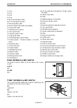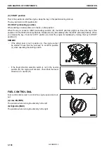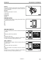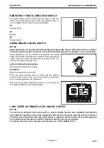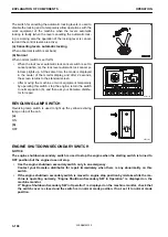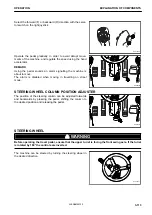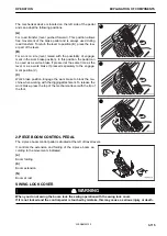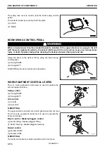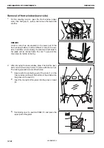
QUICK COUPLER SWITCHES
In order for the hydraulic attachment to work, the switch on the
left instrument panel and the one on the left joystick have to be
both engaged.
For an explanation of these switches operation see “OPERA-
TION OF QUICK COUPLER (6-5)”
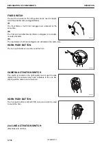
CONTROL LEVERS AND PEDALS
RKA48530
(1) Lock lever
(2) L.H. work equipment control lever
(3) R.H. work equipment control lever
(4) Swing lock cover
(5) Boom swing control pedal
(6) Travel pedal
RKA48360
RKA48513
EXPLANATION OF COMPONENTS
OPERATION
3-110
WENAM00130
Summary of Contents for PW118MR-11
Page 2: ......
Page 9: ...Do not repeatedly handle and lift loads FOREWORD VIBRATION LEVEL 1 7 WENAM00130...
Page 22: ...WENAM00130...
Page 25: ...LOCATION OF SAFETY LABELS RKA64590 SAFETY SAFETY LABELS 2 3 WENAM00130...
Page 72: ...WENAM00130...
Page 74: ...GENERAL VIEW MACHINE EQUIPMENT NAME RKA61930 GENERAL VIEW OPERATION 3 2 WENAM00130...
Page 77: ...CONTROLS AND GAUGES NAMES RKA62690 OPERATION GENERAL VIEW 3 5 WENAM00130...
Page 168: ...SWITCHES RKA63060 EXPLANATION OF COMPONENTS OPERATION 3 96 WENAM00130...
Page 328: ...WENAM00130...
Page 412: ...WENAM00130...
Page 413: ...SPECIFICATIONS 5 1 WENAM00130...
Page 445: ...REPLACEMENT PARTS 7 1 WENAM00130...
Page 461: ......
Page 462: ......


