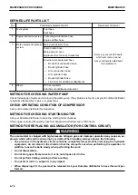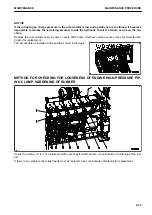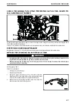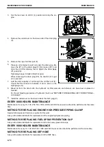
DEFINED LIFE PARTS LIST
No.
Periodical replacement parts
Replacement interval
1
Fuel system
Fuel hose
Spill hose
Every 2 years or 4000 hours,
whichever comes sooner
Ask your Komatsu distributor
for replacement.
2
Engine lubrication system
Turbocharger lubrication hose
Engine oil filter hose
3
Work equipment hydraulic
system
Main pump delivery hose
Pump branch hose
Main pump LS hose
Hydraulic drive fan hose (Intake fan)
External work equipment hose
•
Boom foot connection hose
•
Boom cylinder hose
•
Arm connection hose
•
Arm cylinder hose
•
Bucket cylinder hose
•
Line hose for additional attachment
4
Others
PPC accumulator
Attachment additional accumulator
METHOD FOR CHECKING WATER PUMP
Check for leakage of water and oil around the water pump. If any problem is found, ask your Komatsu distributor
to perform disassembly, repair, or replacement.
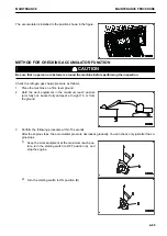
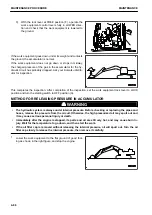
CHECK OPERATING CONDITION OF COMPRESSOR
Ask your Komatsu distributor for inspection.
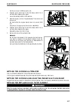
METHOD FOR CHECKING STARTING MOTOR
Ask your Komatsu distributor to have the starting motor checked.
If the engine is started frequently, have this inspection performed every 1000 hours.
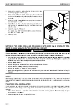
METHOD FOR REPLACING ACCUMULATOR (FOR CONTROL CIRCUIT)
k
k
WARNING
The accumulator is charged with high-pressure nitrogen gas, and improper operation may cause an ex-
plosion which will lead to serious injury or death. When handling, always observe the following.
• The pressure in the hydraulic circuit cannot be completely removed. When removing the hydraulic
equipment, do not stand in the direction that the oil spurts out when performing the operation. In
addition, loosen the bolts slowly when performing the work.
• Do not disassemble.
• Do not bring open flame close to it or do not dispose of it in fire.
• Do not perform drilling, welding or flame-cutting.
• Do not hit or roll it, or subject it to any impact.
• When disposing of it, the gas must be released. Ask your Komatsu distributor to have this work per-
formed.
MAINTENANCE PROCEDURE
MAINTENANCE
4-74
Summary of Contents for PC700LC-11
Page 2: ......
Page 23: ...LOCATION OF SAFETY LABELS 5 SAFETY SAFETY LABELS 2 3...
Page 66: ......
Page 316: ......
Page 396: ......
Page 397: ...SPECIFICATIONS 5 1...
Page 401: ...For 7 6m Boom SPECIFICATIONS SPECIFICATIONS 5 5...
Page 402: ...SPECIFICATIONS SPECIFICATIONS 5 6...
Page 426: ......
Page 427: ...REPLACEMENT PARTS 7 1...
Page 434: ......

