


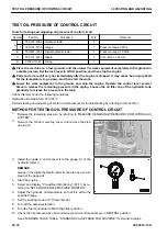
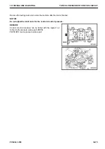


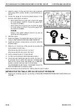


4.
Install the nipple C, and connect the gauge A2 in the hy-
draulic tester A.
REMARK
Gauge in the digital hydraulic tester B can also be used in-
stead of the gauge A2.
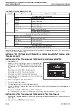
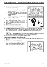
5.
Start the engine.
6.
Select and display “Pre-defined Monitoring” (01/11) by re-
ferring to “SET AND OPERATE MACHINE MONITOR”.
7.
Adjust the hydraulic oil temperature so that it is within the
specified range.
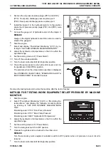
8.
Set the working mode to P (“Power Mode”).
9.
Turn the fuel control dial to MAX (High idle) position.
10. Check that all control levers and control pedals are at
NEUTRAL position.
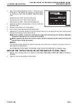
11. Test the oil pressure when the fuel control dial is at MAX
(High idle) and MIN (Low idle) positions.
See STANDARD VALUE TABLE, “STANDARD VALUE TA-
BLE FOR MACHINE” for standard values.
Remove the testing tools and restore the machine after the test is finished.
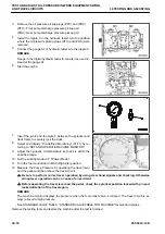
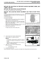
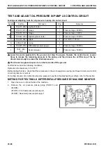
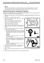
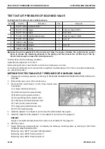
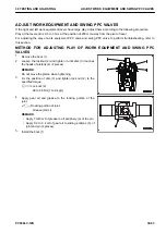
METHOD FOR ADJUSTING OIL PRESSURE IN PUMP PC CONTROL CIRCUIT
When the phenomena shown below occur and PC valves (7) and (8) seem to be defective, adjust them accord-
ing to the following procedure.
• As the working load increases, the engine speed drops largely.
• The engine speed is normal but the work equipment speed is low.
(7): Front pump PC valve
(8): Rear pump PC valve
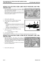
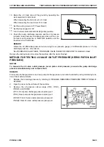
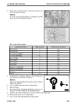
NOTICE
The width across flats of PC valve lock nut is 13 mm, and
the width across flats (inside width) of adjustment screw is
4 mm.
Do not turn the other lock nuts and adjustment screws
since they affect the hydraulic pump performance.
1.
Put matchmarks on the end surface of the adjustment
screw (10).
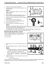
Matchmarks are for these nus to be restored properly if the
restoration is necessary. (This is for the adjustment screw
to return to the original position for the time when turning it
in reverse)
2.
Loosen the lock nut (9).
3.
Rotate adjustment screw (10) clockwise or counterclock-
wise to adjust it.
TEST AND ADJUST OIL PRESSURE IN PUMP PC CONTROL CIRCUIT
30 TESTING AND ADJUSTING
30-78
PC500LC-10R
Summary of Contents for PC500LC-10R
Page 1: ...HYDRAULIC EXCAVATOR SEN06722 00 PC500LC 10R SERIAL NUMBERS 100001 and up...
Page 2: ......
Page 3: ...00 INDEX AND FOREWORD PC500LC 10R 00 1...
Page 76: ......
Page 77: ...01 SPECIFICATIONS PC500LC 10R 01 1...
Page 94: ......
Page 95: ...10 STRUCTURE AND FUNCTION PC500LC 10R 10 1...
Page 177: ...When balanced 10 STRUCTURE AND FUNCTION CLSS PC500LC 10R 10 83...
Page 178: ...When lever is returned to fine control state CLSS 10 STRUCTURE AND FUNCTION 10 84 PC500LC 10R...
Page 179: ...When lever is pulled at a stroke 10 STRUCTURE AND FUNCTION CLSS PC500LC 10R 10 85...
Page 180: ...When lever is in stroke end CLSS 10 STRUCTURE AND FUNCTION 10 86 PC500LC 10R...
Page 377: ...20 STANDARD VALUE TABLE PC500LC 10R 20 1...
Page 407: ...30 TESTING AND ADJUSTING PC500LC 10R 30 1...
Page 583: ...30 TESTING AND ADJUSTING METHOD FOR STARTING UP KOMTRAX TERMINAL PC500LC 10R 30 177...
Page 604: ......
Page 605: ...60 MAINTENANCE STANDARD PC500LC 10R 60 1...
Page 636: ...MAINTENANCE STANDARD OF MAIN PUMP 60 MAINTENANCE STANDARD 60 32 PC500LC 10R...
Page 638: ...MAINTENANCE STANDARD OF SWING MOTOR 60 MAINTENANCE STANDARD 60 34 PC500LC 10R...
Page 641: ...60 MAINTENANCE STANDARD MAINTENANCE STANDARD OF TRAVEL MOTOR PC500LC 10R 60 37...
Page 644: ...MAINTENANCE STANDARD OF CONTROL VALVE 60 MAINTENANCE STANDARD 60 40 PC500LC 10R...
Page 646: ...MAINTENANCE STANDARD OF CONTROL VALVE 60 MAINTENANCE STANDARD 60 42 PC500LC 10R...
Page 648: ...MAINTENANCE STANDARD OF CONTROL VALVE 60 MAINTENANCE STANDARD 60 44 PC500LC 10R...
Page 650: ...MAINTENANCE STANDARD OF CONTROL VALVE 60 MAINTENANCE STANDARD 60 46 PC500LC 10R...
Page 652: ...MAINTENANCE STANDARD OF CONTROL VALVE 60 MAINTENANCE STANDARD 60 48 PC500LC 10R...
Page 658: ...MAINTENANCE STANDARD OF TRAVEL PPC VALVE 60 MAINTENANCE STANDARD 60 54 PC500LC 10R...
Page 668: ...MAINTENANCE STANDARD OF WORK EQUIPMENT LINKAGE 60 MAINTENANCE STANDARD 60 64 PC500LC 10R...
Page 679: ...90 CIRCUIT DIAGRAMS PC500LC 10R 90 1...
Page 692: ......
Page 694: ......
Page 696: ......
Page 698: ......
Page 700: ......
Page 704: ...Symbol Content Buzzer Antenna SYMBOLS USED IN ELECTRICAL CIRCUIT DIAGRAM 90 26 PC500LC 10R...
Page 706: ......
Page 708: ......
Page 710: ......
Page 712: ......
Page 714: ......
Page 716: ......
Page 718: ......
Page 720: ......
Page 722: ......
Page 724: ......
Page 726: ......
Page 728: ......
Page 730: ......
Page 732: ......
Page 734: ......
Page 736: ......
Page 738: ......
Page 740: ......
Page 742: ......
Page 744: ......
Page 746: ......
Page 748: ......
Page 757: ......