MAINTENANCE PROCEDURE
MAINTENANCE
4-38
REPLACE BUCKET SIDE CUTTER, SHROUD
4
WARNING
q
It is dangerous if the work equipment is mistakenly
moved when replacing the bucket side cutters and
shroud.
Set the work equipment in a stable condition, stop the
engine, then set lock lever securely to the LOCK posi-
tion (L).
q
As the locking pin is knocked out with force, there is
danger that the pin may fly out. Check that there is no
one near the machine.
q
Broken pieces may fly during the replacement opera-
tion, so always wear safety glasses, gloves, or other
protective equipment.
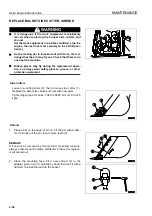
Side Cutters
Loosen mounting bolts (2), then remove side cutter (1).
Replace the side cutter, bolts, and nuts with new parts.
Tightening torque for bolts: 3040 to 3630 Nm (310 to 370
kgm)
Shroud
1.
Place a bar on the head of pin (1), hit the bar with a ham-
mer to knock out the pin, then remove tooth (2).
REMARK
If it cannot be removed by this method, for safety reasons,
always contact your Komatsu distributor to have the replace-
ment carried out.
2.
Clean the mounting face. Fit a new shroud (2) in the
adapter, push in pin (1) partially by hand, then lock it with a
hammer to install the tooth to the bucket.
Summary of Contents for PC450-8
Page 2: ......
Page 3: ...FOREWORD 11 ...
Page 66: ...SAFETY MAINTENANCE INFORMATION SAFETY 2 42 ...
Page 351: ...SPECIFICATIONS 15 ...
Page 355: ...SPECIFICATIONS SPECIFICATIONS 5 5 6 7m Boom PC450 8 ...
Page 356: ...SPECIFICATIONS SPECIFICATIONS 5 6 6 7m Boom PC450LC 8 ...
Page 357: ...SPECIFICATIONS SPECIFICATIONS 5 7 6 7m Boom PC450LCHD 8 ...
Page 359: ...SPECIFICATIONS SPECIFICATIONS 5 9 7 0m Boom PC450 8 ...
Page 360: ...SPECIFICATIONS SPECIFICATIONS 5 10 7 0m Boom PC450LC 8 ...
Page 410: ...SUPER LONG FRONT BOOM AND ARM ATTACHMENTS ANDD OPTIONS 6 50 ...
Page 436: ...OPERATION HIGH REACH DEMOLITION EQUIPMENT 27M 7 26 3 Extend arm cylinder Arm cylinder ...
Page 469: ...INDEX 18 ...
Page 470: ...INDEX 8 2 ...
Page 473: ...COLOPHON 18 ...


