REMARK
• If the light switch is at night mode ON, and the screen is adjusted, it is possible to adjust the brightness
of the monitor screen (night mode).
• If the light switch is at day mode ON, and the screen is adjusted, it is possible to adjust the brightness
of the monitor screen (day mode).
• As long as "*" mark is displayed in the upper right corner of the screen, brightness is automatically re-
stricted by the machine monitor to protect the liquid crystal. Screen adjustment may not change the
screen brightness as long as "*" mark is displayed. However, it is not an error.
• The state of the previous screen display is reflected on the background of the screen adjustment
screen.
Screen adjustment (camera)
Use “Screen Adjustment” (camera) to adjust brightness of the camera screen.
1.
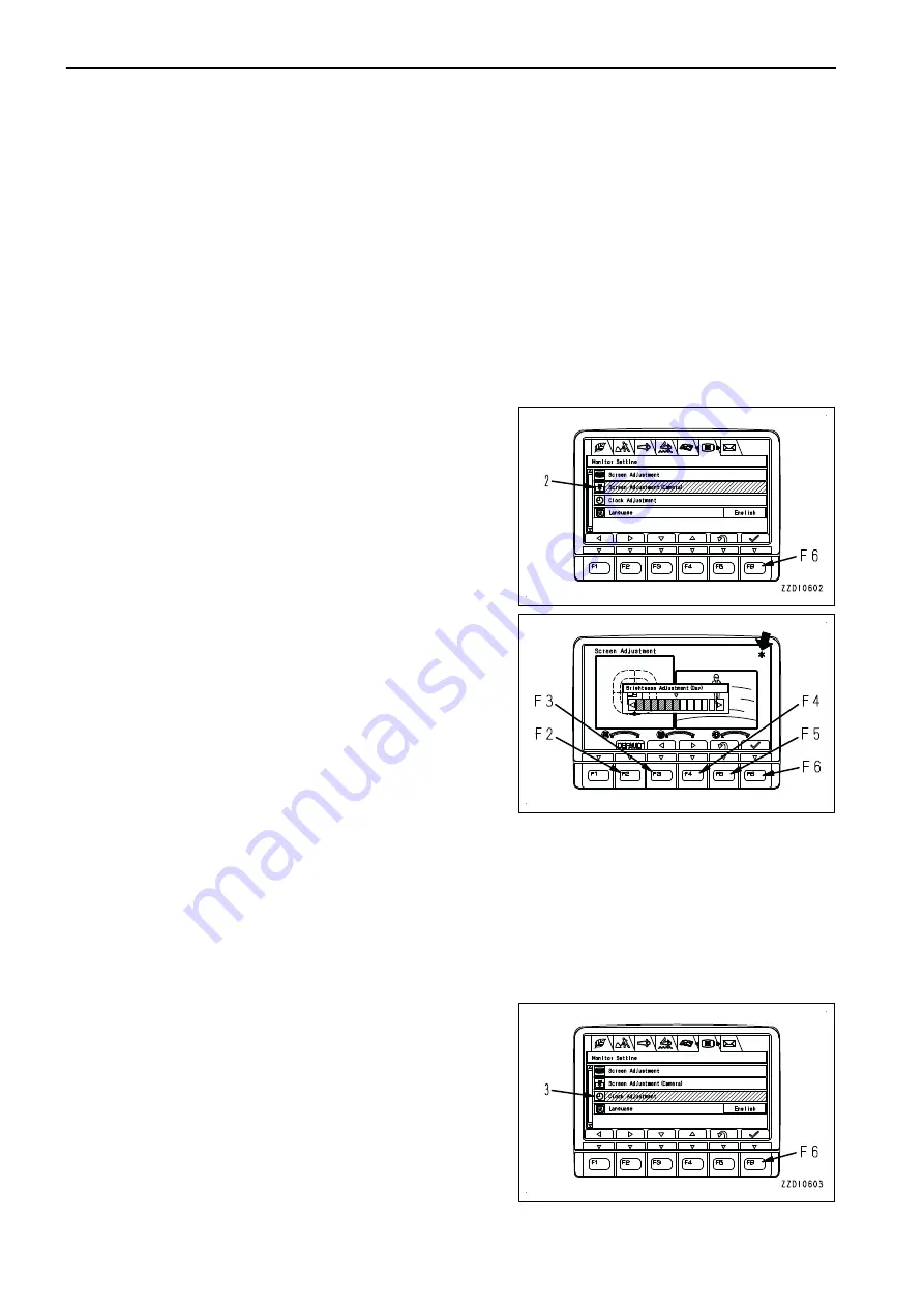
Select screen adjustment (camera) (2) on the “Monitor
Setting” menu screen, then press switch F6.
2.
Use switches F2 to F6 to adjust brightness of the screen.
F2: Resets an adjusted value to default value.
F3: Moves the indicator to the left by one notch.
F4: Moves the indicator to the right by one notch.
F5: Cancels the change and returns the screen to “Monitor
Setting” menu screen.
F6: Accepts the change and returns the screen to “Monitor
Setting” menu screen.
REMARK
As long as "*" mark is displayed in the upper right corner of
the screen, brightness is automatically restricted by the
machine monitor to protect the liquid crystal. Screen ad-
justment may not change the screen brightness as long as
"*" mark is displayed. However, it is not an error.
CLOCK ADJUSTMENT
“Clock Adjustment” menu is used to change the setting of the clock displayed on the standard screen of the
monitor.
1.
Select “Clock Adjustment” (3) on “Monitor Setting” menu
screen, then press switch F6. The screen switches to the
selection menu for the clock adjustment.
The following 5 items can be changed.
(a): “GPS Synchronization”
(b): “Calendar”
(c): “Time”
(d): “12h/24h Mode”
(e): “Daylight Saving Time”
-5
EXPLANATION OF COMPONENTS
OPERATION
3-78
Summary of Contents for PC210-11
Page 2: ......
Page 24: ......
Page 74: ......
Page 352: ......
Page 431: ...SPECIFICATIONS 5 1 ...
Page 435: ...PC210LC 11 PC210NLC 11 SPECIFICATIONS SPECIFICATIONS 5 5 ...
Page 436: ...PC230NHD 11 SPECIFICATIONS SPECIFICATIONS 5 6 ...
Page 459: ...PC230NHD 11 2 Piece Boom ATTACHMENTS AND OPTIONS 2 PIECE BOOM 6 23 ...
Page 470: ... Not including tail swing SUPER LONG FRONT BOOM AND ARM ATTACHMENTS AND OPTIONS 6 34 ...
Page 505: ...REPLACEMENT PARTS 7 1 ...
Page 521: ......


