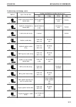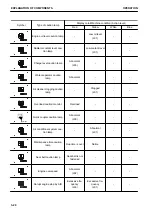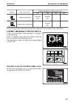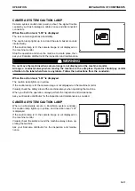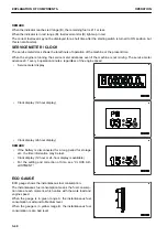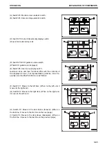
CAMERA SYSTEM CAUTION LAMP
Camera system caution lamp warns about the signal trouble
caused by such as breakage in cables, loose and disconnected
connectors.
When the action level “L03” is displayed
The rear camera signal has abnormality.
The caution lamp lights up in red and the alarm buzzer sounds
intermittently.
If the caution lamp is lit, the camera image is not displayed on
the machine monitor.
Stop the operation and move the machine to a safe place, then
ask your Komatsu distributor for the inspection and maintenance.
k
k
WARNING
Do not move the machine when camera image is not displayed on the machine monitor.
Arrange a conductor always when moving the machine to the safe place. Operator should pay careful
attention to the label when there is any labels. Follow the instructions from the conductor.
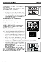
When the action level “L01” is displayed
The caution lamp lights up in yellow.
If the caution lamp is lit, the camera image is not displayed on the machine monitor.
Visually check the safety around the machine always when operating the machine.
When you finish the operation, always perform the inspection and maintenance.
Ask your Komatsu distributor for the inspection and maintenance as needed.
CAMERA SYSTEM CAUTION LAMP
When an abnormality occurs in KomVision system controller,
the caution lamp lights up in yellow, and the action level “L01”
is displayed.
If the caution lamp is lit, the camera image is not displayed on
the machine monitor.
Visually check the safety around the machine always when op-
erating the machine.
Ask your Komatsu distributor for the inspection and mainte-
nance.
OPERATION
EXPLANATION OF COMPONENTS
3-31
Summary of Contents for PC210-11
Page 2: ......
Page 24: ......
Page 74: ......
Page 352: ......
Page 431: ...SPECIFICATIONS 5 1 ...
Page 435: ...PC210LC 11 PC210NLC 11 SPECIFICATIONS SPECIFICATIONS 5 5 ...
Page 436: ...PC230NHD 11 SPECIFICATIONS SPECIFICATIONS 5 6 ...
Page 459: ...PC230NHD 11 2 Piece Boom ATTACHMENTS AND OPTIONS 2 PIECE BOOM 6 23 ...
Page 470: ... Not including tail swing SUPER LONG FRONT BOOM AND ARM ATTACHMENTS AND OPTIONS 6 34 ...
Page 505: ...REPLACEMENT PARTS 7 1 ...
Page 521: ......


