MAINTENANCE PLAN
149
4.7.1.g
CHANGING THE RUBBER TRACK
REMOVING THE RUBBER TRACK
DANGER
•
This operation must be carried out by two persons. One operator must sit in the cab and move the ma-
chine according to the signals of the operator who carries out the check and the adjustment.
•
The shoe tension must be checked with the frame lifted from the ground. Do not operate any control le-
ver while the operator is carrying out the check.
•
During the check, do not remove any part except the shoe to be changed.
•
If the shoe tension cannot be loosened by proceeding as indicated below, contact your Komatsu Utility
Dealer, who will carry out the necessary repairs.
DANGER
•
The grease contained in the hydraulic cylinder is under
pressure. For this reason, do not loosen the greasing
valve (2) giving it more than one turn; if the valve is loos-
ened excessively, it may be pushed out due to the grease
pressure and this is very dangerous for the operator.
Do not loosen any other component in addition to the
valve (2).
•
When assembling or removing the track, before rotating
the sprocket make sure that the grease contained in the
cylinder has been removed.
•
If you notice excessive resistance while injecting grease,
slowly move the machine forward and backward for a
short distance.
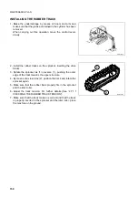
Stop the machine on a firm and level surface, after lowering the
equipment to the ground.
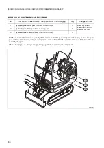
1 - Raise the undercarriage by means of boom and arm.
When carrying out this operation, move the control levers
slowly.
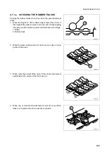
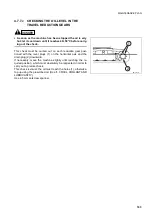
2 - Loosen the screws and remove the cover (1) to reach the ad-
justment point.
Use a 17 mm hexagon spanner.
3 - Gradually loosen the greasing valve (2) to let the grease out;
do not give the valve more than one turn.
Use a 19 mm hexagon spanner.
4 - If the grease does not flow out freely, move the track slowly
forward and backward for a short distance.
5 - Insert the steel tubes (3) inside the track, rotate the sprocket
as if in reverse (4), so that the steel tubes move with the track
and engage in the idler roller; slide the track (5) sidewards
and remove it.
RWA06380
RWA06620
1
2
RWA06630
3
5
4
Summary of Contents for PC12R-8
Page 2: ......
Page 12: ...10...
Page 20: ...18...
Page 21: ...SAFETY AND ACCIDENT PREVENTION...
Page 23: ...SAFETY NOISE AND VIBRATION PLATES 21 RWA05440...
Page 27: ...SAFETY NOISE AND VIBRATION PLATES 25 EMERGENCY EXIT LIFTING POINT RWA00190 RWA04920...
Page 55: ...THE MACHINE AND ITS OPERATIONS...
Page 88: ...86...
Page 120: ...118...
Page 121: ...MAINTENANCE...
Page 177: ...TECHNICAL SPECIFICATIONS...
Page 198: ...196...
Page 199: ...AUTHORISED OPTIONAL EQUIPMENT...


