206
ARRANGEMENT FOR THE INSTALLATION OF THE DEMOLITION HAMMER
6.2.3.2
REMOVING THE HAMMER
6.2.4 MAINTENANCE
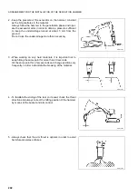
6 - Rotate the lever of the selection valve (3) completely anticlock-
wise.
7 - Start the machine and raise the demolition hammer position-
ing it vertically.
8 - Stop the machine again and lubricate the arm connection
joints (See “4.7.4.a LUBRICATING THE JOINTS”) and the
hammer (see the specific operation and maintenance manu-
al).
9 - Before starting work, check the seals.
DANGER
•
Always wear thick gloves and safety goggles during this
check.
•
To check the system for leaks, use a piece of cardboard or
a wooden board.
RWA19870
3
To remove the hammer, proceed as follows:
1 - Position the hammer on level ground, making sure that it will be firm and stable even after disconnection from
the machine.
2 - Stop the engine and move the hydraulic controls in all directions, in order to completely release the residual
pressures present in the hydraulic circuits.
3 - Turn the ignition key to position «I» and press the hammer control button to release the residual pressure
present in the hammer delivery pipe.
4 -Turn the ignition key to position «O» and remove it.
5 - Disconnect the hammer feeding and draining pipes.
Use 41 and 50 mm spanners.
6 - Fit the sealing plugs of the pipes.
DANGER
•
Make sure that the sealing plugs are tightened correctly and that there are no leaks; if the circuit is inad-
vertently pressurized, small leaks could become thin jets that may hurt the skin or the eyes.
•
Always wear thick gloves and safety goggles during this check.
•
To check the system for leaks, use a piece of cardboard or a wooden board.
7 - Disconnect the hammer from the mechanical constraints as described in paragraph “3.12.5 CHANGING THE
BUCKET”.
The hydraulic system does not require any maintenance operation and inspection other than those prescribed for
the machine.
For the maintenance operations required for the hammer, see the specific operation manual.
Summary of Contents for PC110R-1
Page 2: ......
Page 19: ...17 SAFETY AND ACCIDENT PREVENTION...
Page 51: ...49 THE MACHINE AND ITS OPERATIONS...
Page 126: ...124 PAGE INTENTIONALLY LEFT BLANK...
Page 127: ...125 MAINTENANCE...
Page 190: ...188 PAGE INTENTIONALLY LEFT BLANK...
Page 191: ...189 TECHNICAL SPECIFICATIONS...
Page 198: ...196 PAGE INTENTIONALLY LEFT BLANK...
Page 199: ...197 AUTHORISED OPTIONAL EQUIPMENT...


