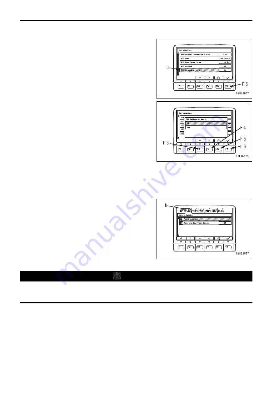
Komatsu D51EX-24 Operation & Maintenance Manual Download Page 118

1.

Select  “ECO  Guidance  Display  at  Key  OFF”  (13)  from
“Configurations” screen, then press switch F6.

2.

The  setting  screen  for  “ECO  Guidance  Display  at  Key
OFF” appears.
ON: Displays ECO Guidance (12) on the end screen.
OFF:  Does  not  display  ECO  Guidance  (12)  on  the  end

screen.

On this screen, it is possible to perform the following oper-
ations with switches F3 to F6.
F3: Moves to the next item (1 line below). When on the last

line, it moves to the first line.

F4:  Moves  to  the  previous  item  (1  line  above).  When  on

the first line, it moves to the last line.

F5: Cancels the setting change and returns to Configurations screen.
F6: Changes the setting and returns the screen to Configurations screen.

MACHINE SETTINGS

Each item of this menu (b) is used for setting items of machine.

REVERSE HYDRAULIC FAN

k

k

 WARNING

After stopping the engine, check around the engine for sticking dry leaves or dirt.
In  particular,  carefully  check  around  the  exhaust  manifold,  turbocharger,  aftertreatment  devices  for
sticking dirt which can cause a fire.
 

The  hydraulic  fan  reverse  mode  (fan  reverse  rotation)  can  be  used  to  remove  insects  and  dirt  sticking  to  the
radiator core by blowing air inward the machine with the fan.
Before starting the hydraulic fan reverse, check that there is no combustible substance in the periphery which
may be sucked in the fan.
In a cold circumstance, perform the cleaning by fan reverse rotation within less than 5 minutes. If the fan re-
verse rotation is performed for a long time, DEF hose may freeze.

EXPLANATION OF COMPONENTS

OPERATION

3-62

Summary of Contents for D51EX-24

Page 1: ...injury or death Operators and maintenance personnel must read this manual before operating or maintaining this machine This manual should be kept inside the cab for reference and periodically reviewed...

Page 2: ......

Page 3: ...uine new Komatsu or Ko matsu approved rebuilt parts or assemblies or others parts of equivalent quality and that the engine be serviced by an authorized Komatsu distribu tor Failure to follow these re...

Page 4: ...peration and Maintenance Manual It is provided on the back of the backrest of operator s seat REMARK When the machine is equipped with the air suspension seat store the Operation and Maintenance Manua...

Page 5: ...complies with the applicable standards and regulations of your country consult your Komatsu distributor before operating the machine FOREWORD READ THIS MANUAL 1 3...

Page 6: ...safety mes sage This signal word indicates an imminently hazardous situation which if not avoided will result in death or serious injury This signal word indicates a potentially hazardous situation wh...

Page 7: ...of the standard deviation of the meas ured time averaged A weighted emission sound pressure level at the operator s position is 2 5dB in accordance with ISO 11201 Sound power level emitted by the mach...

Page 8: ...ines Brake and steering systems Controls hydraulic system and linkages 3 Keep the terrain where the machine is working and travelling in good condition Remove any large rocks or obstacles Fill any dit...

Page 9: ...Do not jump down from the cab or machine Do not repeatedly handle and lift loads FOREWORD VIBRATION LEVELS 1 7...

Page 10: ...front rear right left are determined according to the view from operator s seat E in the direction of travel front of the machine A Front B Rear C Left D Right E Operator s seat F Sprocket VISIBILITY...

Page 11: ...een the nitrogen oxides and ammonia generated from the urea solution and decom poses the nitrogen oxides into nitrogen and water DEF is the abbreviation for Diesel Exhaust Fluid and is represented as...

Page 12: ...s LOCATION OF PRODUCT IDENTIFICATION NUMBER PIN MACHINE SERI AL NO PLATE It is located at front left of the operator s seat The design of the nameplate varies according to the district LOCATION OF ENG...

Page 13: ...erial No Product identification number PIN Manufacturers name Address KOMATSU LTD 2 3 6 Akasaka Minato ku Tokyo 107 8414 Japan Authorised representative Address KOMATSU EUROPE INT Mechelsesteenweg 586...

Page 14: ...B D F G H EI000001 A MACHINE DESIGNATION TYPE E ENGINE POWER B SERIAL NUMBER F PRODUCT IDENTIFICATION NUMBER C YEAR OF CONSTRUCTION G MANUFACTURER D OPERATING MASS H AUTHORISED REPRESENTATIVE SERIAL P...

Page 15: ...ROPE INT Mechelsesteenweg 586 B 1800 Vilvoorde Belgium Declares that this machine D51EX 24 D51PX 24 Fulfils all the relevant provisions of following EC Directives Machinery Directive 2006 42 EC Electr...

Page 16: ...R SAFE OPERATION 2 9 PRECAUTIONS TO PREVENT FIRE 2 10 PRECAUTIONS WHEN GETTING ON OR OFF MACHINE 2 12 DO NOT GET CAUGHT IN WORK EQUIPMENT 2 14 PRECAUTIONS RELATED TO PROTECTIVE STRUCTURES 2 14 UNAUTHO...

Page 17: ...3 183 LOCK 3 183 HANDLE AIR CONDITIONER 3 188 EXPLANATION OF AIR CONDITIONER EQUIPMENT 3 188 METHOD FOR OPERATING TO PREVENT DUST FROM ENTERING INTO CAB 3 189 METHOD FOR CHECKING DURING OFF SEASON 3...

Page 18: ...SCHEDULE TABLE 4 12 MAINTENANCE INTERVAL WHEN DIESEL FUEL MIXED WITH BIO FUEL IS USED 4 13 MAINTENANCE PROCEDURE 4 15 WHEN REQUIRED 4 15 CHECKS BEFORE STARTING 4 42 EVERY 50 HOURS MAINTENANCE 4 42 EVE...

Page 19: ...ENDED FUEL COOLANT AND LUBRICANT 7 4 LUBRICATION CHART 7 4 METHOD FOR USING FUEL COOLANT AND LUBRICANTS ACCORDING TO AMBIENT TEMPERA TURE 7 6 RECOMMENDED BRANDS AND QUALITIES OTHER THAN KOMATSU GENUIN...

Page 20: ......

Page 21: ...se read and make sure that you fully understand the precautions descri bed in this manual and the safety labels on the machine When operating or servicing the machine always follow these precautions s...

Page 22: ...ly When cleaning the safety labels do not use organic solvents or gasoline These may cause the labels to peel off If the safety labels are damaged lost or cannot be read properly replace them with new...

Page 23: ...ution for handling accumulator 7 Caution for adjusting track tension 8 Caution for handling cable 9 Stop rotation during inspection and maintenance 10 Caution for approaching while moving machine 11 P...

Page 24: ...ts SEVERE INJULY or DEATH do the following be fore moving machine or its attachments Honk horn to alert people nearby Be sure no one is on or near machine Use spotter if view is obstructed Follow abov...

Page 25: ...high temperature oil blowing up from the radiator or hydraulic tank will cause personal injury and or burns Never remove the radiator cap or hydraulic tank oil filler when cooling water or hydraulic o...

Page 26: ...tion during inspection and maintenance 09667 A0481 Sign indicates a hazard of rotating parts such as belt Turn off before inspection and maintenance Caution for approaching while moving machine 09806...

Page 27: ...prohibited ROPS or FOPS may provide less protection if it has been structurally damaged or involved roll over Consult Komat su Distributor in that case Always wear seat belt when moving Caution for b...

Page 28: ...injury or death in case of a roll over Always check for damage or wear of the seat belt damage of the connecting brackets and tightness of bolts Adjust seat position to allow full brake pedal travel...

Page 29: ...ATION PRECAUTIONS FOR SAFETY RELATED EQUIPMENT Be sure that all guards covers cameras and mirrors are in their proper position Repair them immediately if they are damaged Understand the using method o...

Page 30: ...ay cause fire Do not use a cellular phone when driving or operating the machine This may lead to mistakes in operation and may cause serious personal injury or death Never bring any dangerous objects...

Page 31: ...pecified place and do not allow unauthorized persons to enter When performing grinding or welding work on the machine move any flammable materials to a safe place before starting Fire caused by accumu...

Page 32: ...g the top of the track or when checking or performing maintenance inside the side cover or when filling the tank with oil Never use them when getting on or off the machine Always face the machine and...

Page 33: ...sonal injury or death PRECAUTIONS WHEN LEAVING MACHINE If the proper procedures are not taken when parking the machine the machine may suddenly move off by itself and this may lead to serious persona...

Page 34: ...d in any other way its strength may drop Any modification is prohibited If the protective structure is damaged or deformed by falling objects or by rolling over its strength will be reduced and it wil...

Page 35: ...rt or operate the engine in a place where there is good ventilation If the engine or ma chine must be operated inside a building or underground where the ventilation is poor take steps to ensure that...

Page 36: ...PRECAUTIONS WHEN WORKING ON LOOSE GROUND Avoid driving or operating the machine near the edge of cliffs road edges and deep ditches The ground may be weak in such areas If the ground should collapse...

Page 37: ...hould give signals When working in dark places turn on the working lamp and headlamps installed to the machine and set up additional lighting in the work area if necessary Stop operations if the visib...

Page 38: ...s work to ensure that there is no problem with the operation of the machine If these checks are not performed properly problems may occur with the operation of the machine and there is a danger which...

Page 39: ...Before charging or starting the engine with a different power source melt the battery electrolyte and check that there is no leakage of electrolyte before starting START ENGINE WITH JUMPER CABLES If a...

Page 40: ...the area around the machine there is danger that they may be hit or caught by the ma chine and this may lead to serious personal injury or death Always observe the following before traveling Always o...

Page 41: ...in tunnels under bridges under electric wires or other places where the height is limited operate slowly and be extremely careful not to let the machine body or work equipment hit anything PRECAUTION...

Page 42: ...hen working on slopes Frozen road becomes soft when the temperature rises and the machine may tip over or be not able to es cape Be particularly careful when working on frozen road It is dangerous tha...

Page 43: ...f adequate strength Be sure that the ramps are wide long and thick enough to provide a safe loading slope Take suitable steps to prevent the ramps from moving out of position or coming off 1 Chocks 2...

Page 44: ...s confirm that the wire rope or drawbar used for towing has ample strength for the weight of the ma chine being towed Never use the wire rope which has cut strands A re duced diameter B or kinks C The...

Page 45: ...e clean the tidy to enable you to perform operations safely If the work place is not kept clean and tidy there is the danger that you will trip slip or fall over and injure your self SELECT SUITABLE P...

Page 46: ...equip ment lock lever 2 to FREE position F operate the blade control lever and the ripper control lever to RAISE and LOWER position 2 to 3 times repeatedly to release the re maining pressure in the h...

Page 47: ...And take steps to prevent unauthorized persons from entering the storage area PRECAUTIONS FOR WORKING AT HIGH PLACES When working at high places use a step ladder or other stand to ensure that the wo...

Page 48: ...the work equipment and machine are not supported they may come down and it may cause serious per sonal injury or death Never use concrete blocks for supports Concrete blocks may break under even ligh...

Page 49: ...lphuric acid Any mistake in handling may cause serious personal injury explosion or fire Always ob serve the following When handling the battery always wear protective eye glasses and rubber gloves If...

Page 50: ...cap or plug slowly to release the internal pressure and remove the cap or plug PRECAUTIONS FOR HIGH TEMPERATURE PARTS To prevent burns from touching high temperature parts when checking or performing...

Page 51: ...loose or oil or fuel is found to be leaking from the mount stop operations and tighten to the specified torque If any damaged or deformed hoses or piping are found consult your Komatsu distributor Rep...

Page 52: ...mbly has a powerful spring that acts to reduce the impact on the idler If it is disassembled by mistake the spring may shoot out and cause serious personal injury or death If it is necessary to disass...

Page 53: ...SPOSING OF WASTE MATERIALS 2 33 and MAINTENANCE OF AIR CONDITIONER 2 33 PRECAUTIONS FOR DISPOSING OF WASTE MATERIALS To prevent pollution pay full attention to the way to dispose of waste materials Al...

Page 54: ...and cause serious personal injury or death It is difficult to judge the remaining life of these components from external inspection or the feeling when operating so always replace them at the specifie...

Page 55: ...tainer for storage Only open containers in a well ventilated area When storing DEF avoid direct sunlight Always use the original container it came in Do not exchange the con tainer of DEF with anothe...

Page 56: ......

Page 57: ...OPERATION Please read and make sure that you understand the SAFETY section before reading this section 3 1...

Page 58: ...ver 3 ROPS cab 4 Sprocket 5 Lift cylinder 6 Idler 7 Work equipment frame 8 Angle cylinder 9 Track frame 10 Track 11 Radiator grille 12 Tilt cylinder 13 DEF pump 14 DEF tank 15 Battery disconnect switc...

Page 59: ...rol dial 4 Joystick steering directional and gear shift lever 5 Rear lamp switch 6 Headlamp switch 7 Machine monitor 8 Foot heater switch 9 Engine shutdown secondary switch 10 Starting switch 11 Decel...

Page 60: ...lot lamp 12 Parking brake pilot lamp 13 Work equipment lock pilot lamp 14 Aftertreatment devices regeneration display 15 Message display 16 Operating mode display 17 Steering mode display 18 Preheatin...

Page 61: ...NE MONITOR EQUIPMENT AA Standard screen EE Warning or Error screen DD Guidance screen 1 Warning display 2 Pilot display 3 Meter display 4 Speed range display 5 Monitor switch area 6 Guidance icon disp...

Page 62: ...mode display screen HH After gear shift mode display screen HH is displayed for 2 seconds the screen switches to standard screen AA REMARK When the engine is started the battery voltage may suddenly d...

Page 63: ...ITUATION When the starting switch is turned to OFF position end screen JJ or KK is displayed for 5 seconds then the display goes out End screen when any message has been re ceived If there is any mess...

Page 64: ...clear an input character at a time On the ID number input screen LL with SKIP press switch F1 and the screen changes to the Check Before Starting screen BB without inputting ID number REMARK Contact...

Page 65: ...lity when starting the engine the check before starting screen BB changes to the maintenance time warning screen CC warning screen FF 1 or error screen EE After displaying the checks before starting s...

Page 66: ...the detail of the current abnormality The Current Abnormality screen is displayed BASIC OPERATION OF MACHINE MONITOR WHEN TROUBLE OCCURS WHILE OPERATING MACHINE If any abnormality occurs during opera...

Page 67: ...achine monitor indicates presence of an ab normality of the machine Take appropriate actions following the list of action level displays and required actions The caution lamp that lights up in red whe...

Page 68: ...ndard screen When 1 type of caution is generated it is displayed on caution lamp 2 When 2 types of cautions are generated they are displayed on caution lamps 2 and 3 When 3 types or more of caution ar...

Page 69: ...Degree of ur gency Action lev el Buzzer Caution lamp Required action High Low L04 Sounds contin uously Lights up in red Stop the machine immediately and ask your Komatsu distrib utor for inspection a...

Page 70: ...is case stop the machine and lower the engine speed to low idle with the fuel control dial or the decelerator brake pedal The engine output or engine speed limitation is reset Caution lamps and displa...

Page 71: ...gine stop ped at high temperature L01 Engine system caution lamp Abnormal L04 L03 Abnormal L01 Parking brake system caution lamp Abnormal L04 L03 Abnormal L01 Fan control system caution lamp Abnormal...

Page 72: ...t see the section of each caution lamp CURRENT ABNORMALITY DISPLAY SWITCH If there is any abnormality currently generated is displayed on top of switch F5 While is displayed press switch F5 to shift t...

Page 73: ...ated and the engine speed drops Stop operations and run the engine at low idle until the caution lamp changes to the normal display color blue at a proper temperature When temperature is proper The ca...

Page 74: ...and ask your Komatsu distribu tor for inspection and maintenance When action level L03 is displayed The caution lamp lights up in red and the alarm buzzer sounds intermittently Stop the operation and...

Page 75: ...and maintenance performed As needed ask your Komatsu distributor for inspection and maintenance BRAKE SYSTEM CAUTION LAMP The brake system caution lamp warns about abnormality in the brake system When...

Page 76: ...hen clogged The caution lamp lights up in red and action level L02 is dis played The alarm buzzer sounds intermittently HST filter is clogged Stop the engine and replace the HST oil filter cartridge w...

Page 77: ...rol system When lightning in red With Action level L04 DEF tank level is too low Inducement status is Severe Inducement Engine power is under heavy deration With Action level L03 DEF tank level is low...

Page 78: ...ution lamp lights up in red and the alarm buzzer sounds continuously Stop the machine immediately and ask your Komatsu distribu tor for inspection and maintenance When action level L03 is displayed Th...

Page 79: ...maintenance When action level L01 is displayed The caution lamp lights up in yellow Some functions may be restricted for use but the machine can operate When you finish the operation always have the i...

Page 80: ...orms one unit with the fuel prefilter The water separator is installed at the bottom of the fuel prefil ter as detachable condition AIR CLEANER CLOGGING CAUTION LAMP Air cleaner clogging caution lamp...

Page 81: ...dard screen The lighting time of maintenance due time notice yellow has been initially set to 30 hours but it can be changed To change the setting ask your Komatsu distributor For operations on the Ma...

Page 82: ...gauge 18 Multi gauge 19 Fuel gauge 20 DEF level gauge 21 Fuel consumption gauge PILOT DISPLAY The pilot display at the top of the screen consists of the pilot lamps to check the actuation of each fun...

Page 83: ...blue B There is any read message to which no reply has been made OFF No messages OPERATING MODE DISPLAY The currently set operating mode is displayed on the operating mode display The display of the o...

Page 84: ...amp flashes PARKING BRAKE PILOT LAMP The parking brake pilot lamp lights up when the parking brake lever is in LOCK position It goes out when the parking brake lever is set to FREE posi tion When the...

Page 85: ...ws A Lights up when the mode is set to NORMAL mode B Lights up when the mode is set to FINE mode Steering mode is set by depressing the customize switch For details of the setting method see CUSTOMIZE...

Page 86: ...r or when switch F5 is pressed Overload prevention guidance If the machine is overloaded during work overload prevention message is displayed on the machine monitor Fuel consumption can be reduced by...

Page 87: ...tor The guidance for engine stop operation during regeneration of the aftertreatment devices goes out 10 seconds later or when switch F5 is pressed SPEED RANGE DISPLAY The speed range display section...

Page 88: ...dicator goes beyond A of red range during operations the overheat prevention system operates A to B Red range A to C Green range C to D White range The overheat prevention system is actuated as follow...

Page 89: ...w idle or stop it and wait for the hydraulic oil temperature to drop Display H when temperature is correct Background K of hy draulic oil temperature caution lamp lights up in blue Display J when abno...

Page 90: ...the engine speed By pressing switch F4 on the standard screen you can switch the clock display and service meter display REMARK If the battery is disconnected for a long period for storage etc the ti...

Page 91: ...UEL CONSUMPTION GAUGE Fuel consumption gauge shows the average fuel consumption of the machine A Shows the average fuel consumption of a day from 0 00 a m of the day to 0 00 a m of the next day B Show...

Page 92: ...rn the starting switch to ON position MONITOR SWITCHES 1 Function switch 2 Buzzer cancel switch 3 Operating mode selector switch 4 Pedal mode selector switch 5 Gear shift mode selector switch 6 Revers...

Page 93: ...uidance erase switch While ECO guidance is displayed F Switch F6 User menu display switch Guidance icons and their functions differ with the contents of the displayed screen but representative guidanc...

Page 94: ...pages where the control methods of respective screens are explained BUZZER CANCEL SWITCH Buzzer cancel switch is used to stop the alarm buzzer for the warning item where there is an abnormality The bu...

Page 95: ...ON position the decelera tor mode is selected The selected mode is displayed at the top of the screen GEAR SHIFT MODE SELECTOR SWITCH The gear shift mode selector switch is used to switch the gear sh...

Page 96: ...E 1st Speed Setting 2 1 0 1 2 5 levels 2nd Speed Set ting 2 1 0 1 2 5 levels 3rd Speed Set ting 2 1 0 3 levels OPERATING MODE Select Operating Mode on Mode Select screen and press switch F6 Operating...

Page 97: ...peration Reverse travel speed can also be set with the reverse travel speed setting switch LOAD DISPLAY Select Load Display on Mode Select screen and press switch F6 Display Non display of load graph...

Page 98: ...ther from the position where the operating effort becomes large and the machine makes pivot turn When the starting switch is turned to ON position the normal mode is selected The selected mode is disp...

Page 99: ...ou can increase or decrease the speed in 2 levels each 2 Increases 2 levels from preset 2nd travel speed 1 Increases 1 level from preset 2nd travel speed 0 Preset 2nd travel speed 1 Decreases 1 level...

Page 100: ...see 1ST TRAV EL SPEED SETTING METHOD FOR SETTING EACH ITEM AND SAVING MEMORY 1 Press the switch F3 or F4 on Mode Select screen to set the yellow cursor to the target item of setting change and then pr...

Page 101: ...s displayed 2 Press switch F3 or F4 to move the yellow cursor to a mem ory number M1 to M5 to call out As the cursor is set to the number the setting stored in the memory is displayed in the right sid...

Page 102: ...d while the machine travels in reverse the operating mode is changed however it is not displayed on the screen It is possible to change the gear shift mode by pressing the gear shift mode selector swi...

Page 103: ...rd screen and check the content of the error or warning display While the caution lamp is flashing if no lever is operated for 10 seconds or more the screen automatically returns to the standard scree...

Page 104: ...s switch F4 while the clock is displayed the service meter is displayed instead of the clock If you press switch F4 while the service meter is displayed the clock is displayed instead of the service m...

Page 105: ...te value indicated by the multi gauge is as fol lows Engine speed 1 500 rpm 2 1000 rpm 3 1500 rpm 4 2000 rpm 5 2750 rpm 6 3000 rpm 1 to 5 Green range 5 to 6 Red range During operation try to keep the...

Page 106: ...rge during engine running is not performed normally Stop the operation move the machine to a safe place and then ask your Komatsu distributor for the inspection and maintenance Drawbar pull 1 0 W 2 0...

Page 107: ...g menu screens a Energy Saving Guidance b Machine Setting c Aftertreatment Devices Regeneration d SCR Information e Maintenance f Monitor Setting g Mail Check These menus a to g are for setting and co...

Page 108: ...Operation of manual stationary regeneration d SCR Information Check of DEF level Information on DEF system e Maintenance Check and reset of various maintenance times f Monitor Setting Screen Adjustme...

Page 109: ...end menu it moves to the left end menu F3 Moves to the next item 1 line below When on the last line it moves to the first line on the next page F4 Moves to the previous item 1 line above When on the f...

Page 110: ...Fuel Consump tion Actual Working Fuel Consumption Idling Hours and E mode time ratio on daily basis or on a split measurement peri od basis are displayed Operation on the Operation Records screen On...

Page 111: ...ds screen F5 Returns the screen to the Energy Saving Guidance screen REMARK ECO guidance denotes displaying the guidance for energy sav ing operation This display may appear on the standard screen whi...

Page 112: ...of fuel consumption and fuel consumption rate may differ from the actual value due to the operating con ditions of the customers fuel used weather or work contents etc Switching of displayed graph Pr...

Page 113: ...ing of the Average Fuel Consumption Display Switching of the Display Non display of ECO gauge and drawbar pull gauge Setting of the ECO Gauge Display Fuel Target Value Switching of the Display Non dis...

Page 114: ...Moves to the previous item 1 line above When on the first line it moves to the last line on the previous page F5 Cancels the setting and returns to Configurations screen F6 Changes the setting and re...

Page 115: ...creen When you stop the measurement select Operation Records 1 screen or ECO Guidance Records 2 screen on Energy Saving Guidance menu a Move to each screen press measurement stop switch F1 STOP SWITCH...

Page 116: ...es to the first line on the next page F4 Moves to the previous item 1 line above When on the first line it moves to the last line on the previous page F5 Cancels the setting and returns to Configurati...

Page 117: ...tting screen appears ON Displays ECO Guidance 10 on the standard screen OFF Does not display ECO Guidance 10 on the stand ard screen On this screen it is possible to perform the following operations w...

Page 118: ...ns screen MACHINE SETTINGS Each item of this menu b is used for setting items of machine REVERSE HYDRAULIC FAN k k WARNING After stopping the engine check around the engine for sticking dry leaves or...

Page 119: ...ishing the warm up operation set the fuel control dial to Low idle MIN position 4 Stop the engine 5 Open the hydraulic tank inspection cover and fuel tank inspection cover 6 Remove the undercover 7 Tu...

Page 120: ...ent condition until aftertreatment devices regeneration display A goes out After the lamp goes out the fan can rotate in reverse by in creasing the engine speed If the parking brake lever or work equi...

Page 121: ...ngine is running normally The parking brake lever and work equipment lock lever are in LOCK positions The engine coolant temperature and hydraulic oil temperature are high and there is no need of idli...

Page 122: ...anges to the countdown screen At this time the engine speed is fixed to Low idle MIN position If you set the parking brake lever or work equipment lock lever to FREE positions countdown stops and the...

Page 123: ...Hydraulic Oil Filter Change 2000 Hydraulic Oil Change 2000 HST Oil Filter Change 2000 KCCV Filter Change 2000 DEF Filter Change 2000 DEF Tank Washing 4500 A Maintenance item B Default maintenance int...

Page 124: ...ing 30 hours consult your Komatsu distributor Operations on Maintenance Due Time Reset screen On Maintenance screen if switch F6 is kept pressed for 1 5 seconds or more the screen changes to Mainte na...

Page 125: ...of the monitor screen night mode If the light switch is at day mode ON and the screen is adjusted it is possible to adjust the brightness of the monitor screen day mode As long as mark is displayed in...

Page 126: ...the first line it moves to the last line F5 Cancels the change of setting and returns to the Monitor Setting menu screen F6 Changes the setting and returns to the Monitor Setting menu screen ADJUST CA...

Page 127: ...ing screen is displayed OFF Guide lines Outline A Center Line B are not displayed Outline Only outlines A that indicate the machine width and the distance from the rear end of the ma chine are display...

Page 128: ...nu enables automatic setting of the monitor s date and time in accordance with the clock of GPS F3 Moves to the next item 1 line below Moves to the top line when on the bottom line F4 Moves to the pre...

Page 129: ...isplay B If it is not necessary to change the month press switch F6 F3 Calendar goes back 1 month F4 Calendar advances 1 month F5 Cancels change and returns to the year setting screen F6 Proceeds to s...

Page 130: ...the minute 3 When minute display E is highlighted in yellow operate the switches as follows to change minute display E If it is not necessary to change the minute press switch F6 F3 The time goes bac...

Page 131: ...to the next item 1 line below Moves to the top line when on the bottom line F4 Moves to the previous item 1 line above Moves to the bottom line when on the top line F5 Cancels change and returns to Cl...

Page 132: ...ID number A of ID key inserted into the starting switch can be checked with ID key information menu 5 OPERATOR ID You can check and change the Operator ID which is under identification on the Operato...

Page 133: ...be changed A message is displayed below and the screen returns to the Monitor Setting menu screen On the Monitor Setting menu screen the inputted ID is displayed in the column of Operator ID When you...

Page 134: ...is not changed WHEN OPERATOR IDENTIFICATION FUNCTION IS AVAILABLE WITHOUT SKIP When the operator identification function is available without SKIP the identified ID number is not displayed in the Oper...

Page 135: ...ard screen lights up Message is distinguished as follows according to the lighting states of User Message 1 Lights up in green A There is unread message Lights up in blue B There is any read message t...

Page 136: ...ion menu g The selected item number is written in place 5 of the message text Input the number by using the monitor panel switch Each switch corresponds to the value shown on the right side below the...

Page 137: ...switch at this position while the engine is running C START position This is the position to start the engine Keep the key at this position during cranking and release it immediately after the engine...

Page 138: ...he position where the dial is turned fully to the right REMARK If the work is relatively low load operation and also does not require the high speed travel turn back the fuel control dial a little to...

Page 139: ...alf dry Foreign material caught in arm or blade Snow or ice sticking to arm or blade This switch is also used as the window washer switch The switch is operated as follows Switches LH FF RH and RR a O...

Page 140: ...on is set to day mode C OFF position Lamps go out The monitor illumination is set to day mode REAR LAMP SWITCH Use the rear lamp switch to light up the rear lamp A ON position Rear lamp lights up B OF...

Page 141: ...the switch cover is closed and the switch is in the NORMAL position If not set it to the NOR MAL position 1 Raise cover C and open it 2 Turn the engine shutdown secondary switch to upper posi tion a...

Page 142: ...gh The lamp inside the switch lights up by operating the switch AIR CONDITIONER SWITCH Air conditioner switch is used to control the air conditioner A Air conditioning mode selector switch B Blower se...

Page 143: ...ves freely under external force REMARK The blade is not set in FLOAT mode until the lever is moved to LOWER stroke end To set the blade in FLOAT mode move the lever to LOW ER stroke end while pressing...

Page 144: ...D Blade is stopped and held in this position H RIGHT angle Blade is angled rightward REMARK If the angling operation is performed while the blade con trol lever is not in HOLD position while either or...

Page 145: ...essing effort increases If you depress it further the mechanical brake is applied PARKING BRAKE LEVER k k WARNING When leaving the operator s seat set the parking brake lever securely to LOCK position...

Page 146: ...set the work equipment lock lever to LOCK position L When pulling up or pushing down the work equipment lock lever be careful not to touch the blade control lever The work equipment lock lever is a l...

Page 147: ...ion it returns to A or B and the machine travels straight If you perform steering operation by supporting your hand with lever guide G performance of steering operation im proves Counter rotation turn...

Page 148: ...rking brake lever is locked P is displayed OTHER EQUIPMENT DOOR OPEN LOCK Use the door lock to fix the door in position after opening it 1 Push the door against the door catch 1 The door is fixed to t...

Page 149: ...the key is turned when it is not inserted all the way to the end it may break CUP HOLDER This is for keeping a beverage can cup etc If you put them on the other place than cup holder they will fall d...

Page 150: ...y NOTICE Do not use this as a power supply for 12 V equipment This will cause failure of the equipment If cigarette lighter 1 is removed its socket can be used as a power source The capacity of the ci...

Page 151: ...he fuse be sure to turn the starting switch to OFF position and after confirming that the system operating lamp is not lit set the battery disconnect switch key to OFF position The fuses protect the e...

Page 152: ...ly 2 9 15 A Starting switch 10 30 A Engine controller 11 20 A Spare power supply 12 20 A Spare 13 5 A Key accessory engine 14 15 10 A Machine controller 2 16 10 A Monitor panel 17 5 A System operating...

Page 153: ...ot work or the preheater does not work a fusible link built in the wiring harness is suspected to be disconnected Check and replace the fusible link Open the hydraulic tank inspection cover on the lef...

Page 154: ...It can be installed at the rear part of the operator s seat Mounting bracket optional is necessary for installation For details of the parts necessary for installation consult your Komatsu distributor...

Page 155: ...tery disconnect switch in ON position except the following cases When the machine is stored for a long time more than a month When repairing the electrical system When performing electric welding When...

Page 156: ...in green when the control ler is turned on Usually it goes out in 5 to 6 minutes after the starting switch is turned to OFF position Before operating the battery disconnect switch check that sys tem...

Page 157: ...s well for abnormality Be careful not to hit your head etc against radiator grille when opening it Check the hose and piping which moves with radiator grille for crack and other damage METHOD FOR OPEN...

Page 158: ...lushed Never reuse the filter element since it can cause a performance decre ment of engine and it result in a failure even if it is cleaned HANDLE UREA SCR SYSTEM WARNING k k WARNING Exhaust gas temp...

Page 159: ...ge the filter may cause a malfunction of the equipment Do not paint the DEF injector or pump Cover the pump and injector whenever you paint around them Use only DEF which complies with the quality sta...

Page 160: ...urs until regeneration is performed When caution lamp 2 comes on in yellow after the end of ongoing work stops the machine in a safe area and acti vate manual stationary regeneration High level requir...

Page 161: ...no persons or combustible materials around the exhaust pipe outlet and aftertreatment devices 3 Set the parking brake lever and work equipment lock lever to LOCK position L 4 Set the fuel control dia...

Page 162: ...ENT DEVICES REGENERATION DISABLE If necessary it is possible to disable automatic regeneration Also it is possible to stop regeneration in progress Procedures to disable automatic regeneration 1 When...

Page 163: ...n to open the Aftertreatment Devices Regeneration screen 2 With regeneration disable highlighted push function switch F6 to disable regeneration It may be impossible to disable regeneration during reg...

Page 164: ...r start working only after a proper amount of DEF is thawed This may be noticed as a delay in the start of functioning of the pump and the injector The heating system is also activated automatically d...

Page 165: ...d work equipment lock lever to LOCK position or the joystick steering directional and gear shift lever and blade control lever is in NEUTRAL position for over 3 seconds SCR Information screen of the u...

Page 166: ...he DEF level gauge light up in red The DEF level caution lamp 1 lights up in red Action Level L03 is displayed in red 5 Press F6 to display the SCR Information screen Inducement status 4 3 Engine powe...

Page 167: ...evels Warning Continuous Warning Low level Inducement and Severe In ducement The Inducement strategy includes visual alert by the DEF system caution lamp and Action Level displayed on the machine moni...

Page 168: ...cted by the Action Level table Inducement advances to Continuous Warning Continuous Warning The audible alert sounds in repetition of three beeps and a pause The DEF system caution lamp 1 lights up in...

Page 169: ...r heavy deration Due to the further deration of engine power capability the machine will be limited further Severe Inducement is the final status of Inducement Unless all the SCR system abnormalities...

Page 170: ...butor The content of the warning can be checked on the SCR Information screen of the user menu Perform the following procedure Press F6 to display the SCR Information screen If either the parking brak...

Page 171: ...e of Continuous Warning is 5 hours The remaining time Hours and Minutes till the next Induce ment status of Low level Inducement is displayed in the column 6 of SCR Information screen In Low level Ind...

Page 172: ...use the engine power restoration function to move the machine to a safe place and contact your Komatsu distributor TEMPORARY RESTORATION FROM INDUCEMENT Temporary Restoration from Inducement is the o...

Page 173: ...Temporary Resto ration from inducement is displayed in the column 1 of the pop up menu window B 4 Press F6 while the Engine Power Recovery window is displayed Temporary Restoration from Inducement is...

Page 174: ...ducement other than the amount of DEF in the tank If another abnormality abnormalities is detected within 40 hours after the previous abnormalities were corrected regardless of the level of the previo...

Page 175: ...d with the KOM TRAX device by using satellite communication or portable radio communication The GPS Global Positioning System receiver and communication system are equipped in the vehicle man agement...

Page 176: ...eck for dirt accumulated around the engine and radiator Also check for combustible materials dry leaves twigs etc around the battery exhaust pipe aftertreatment devices turbocharger or other high temp...

Page 177: ...s for leakage of exhaust gas If any problem is found ask your Komatsu distributor for repair 15 Check around SCR for exhaust gas leakage Check the SCR connections and the pipe for leakage of exhaust g...

Page 178: ...o catch the water and sediment at the end of the drain hose 3 3 Loosen the drain valve 4 and drain the water 4 When fuel starts draining from the drain hose 3 tighten the drain valve 4 immediately 5 R...

Page 179: ...above H line It may damage the oil circuit and cause the oil to spurt out Set the work equipment to the posture shown in the figure be fore checking hydraulic oil level or adding oil 1 Place the mach...

Page 180: ...e left side of the machine 2 Check that the coolant level is between FULL and LOW marks of reservoir tank 1 When the coolant level is between FULL and LOW marks The coolant level is proper When the co...

Page 181: ...the blowby gas However if the coolant level is normal it is not a problem Prepare a container to catch the drained oil 1 Open the engine side covers 1 and 2 on the left side of the machine 2 Open the...

Page 182: ...se the engine side covers 1 and 2 METHOD FOR CHECKING DUST INDICATOR 1 Open the engine side cover on the left side of the machine 2 Check if the inside yellow piston of dust indicator 1 is lap ped ove...

Page 183: ...r capacity is proper Perform inspection to confirm that there is no disconnection or trace of short circuiting in the electric wiring and no damage to the coating Perform inspection to confirm that th...

Page 184: ...gasoline is added into the tank it can cause a fire Some fluids or agents added can create and emit a toxic gas When opening the cap of DEF tank of the machine the ammonia vapor may escape Keep your f...

Page 185: ...se a funnel to add DEF the strainer which is set at the filler port may be broken Do not use a funnel When using a portable refill container use it up each time If any of it is left completely seal it...

Page 186: ...DEF through the filler port 2 until float 4 reaches the line F 5 Line 6 in the sight gauge indicates approximately 5 below the line F and the line 7 indicates approxi mately 10 below the line F The l...

Page 187: ...to the ground stop the engine and then perform the operation When opening the DEF tank filler port cover do not release the cover until the cover opens to be horizontal Do not put anything other than...

Page 188: ...NING AND CLOSING DEF TANK FILLER PORT COVER 6 Check the positions of a to d shown in the figure 7 Put the BIB container gently on it 8 Turn the DEF tank filler port cap 2 counterclockwise O and open i...

Page 189: ...ches the line F 5 Line 6 in the sight gauge indicates that it is approximately 5 below the line F and the line 7 indicates that it is ap proximately 10 below the line F The line 7 is the adding line w...

Page 190: ...lb or disconnected wire are the possible causes Ask your Komatsu distributor for repairs 4 After finishing the check turn the head lamp to OFF posi tion c and turn the rear lamp to OFF position e 5 Tu...

Page 191: ...IN ENGINE COMPARTMENT Check that there is no deposit inside the engine compartment particularly around the turbocharger exhaust manifold and aftertreatment devices If there is any deposit remove it ME...

Page 192: ...n the joystick steering directional and gear shift lever to NEUTRAL po sition N immediately 5 Return the starting switch back to OFF position A METHOD FOR TESTING DECELERATION BRAKE PEDAL k k WARNING...

Page 193: ...USPENSION SEAT LOW BACK SEAT METHOD FOR ADJUSTING SEAT IN FORE AND AFT DIRECTION 1 Pull up the fore aft adjustment lever and set the seat to the desired position Fore and aft adjustment range 180 mm 1...

Page 194: ...to make the seat higher and push it down to make the seat lower Adjust it so that the weight adjustment indicator 2 enters the green range You can adjust the height by operating lever 1 in the green r...

Page 195: ...ture is above approximately 20 C the heater does not operate even if the switch is turned on MECHANICAL SUSPENSION SEAT if equipped METHOD FOR ADJUSTING SEAT IN FORE AND AFT DIRECTION 1 Pull up the fo...

Page 196: ...r back is not touching the backrest it may suddenly move forward 2 After adjusting release the lever METHOD FOR TILTING SEAT Pull up the tilt adjustment lever and adjust the front angle of the seat To...

Page 197: ...he seat is moved backward turn knob 1 to adjust Weight adjustment range 60 to 150 kg 2 After adjusting the weight return the crank of knob 1 2 Adjust the height by turning knob 1 in the green range Th...

Page 198: ...Turn on the seat heater switch a OFF position b ON position The backrest and seat surface are heated When the seat heater switch is turned on the heater in the seat operates When the seat surface tem...

Page 199: ...krest it may suddenly move forward 2 After adjusting release the lever METHOD FOR TILTING SEAT 1 Pull up the tilt adjustment lever and adjust the front angle of the seat To raise the front of the seat...

Page 200: ...y for 1 minute or longer since such practice can damage the air compressor The seat height is adjusted pneumatically and in stepless 1 When adjusting the seat height pull up the height adjust ment lev...

Page 201: ...he mirrors before starting work If they are not adjusted properly you cannot secure the visibility and may be injured or may lead to a serious personal injury or death Adjust the mirror by moving it A...

Page 202: ...t belt when fastening REMARK The date indicated on the seat belt is the manufactured date It is the start of the 5 year period It is not the start of the 3 year period of actual usage CHECK SEATBELT C...

Page 203: ...KS BEFORE STARTING ENGINE k k WARNING When starting the engine check and make sure park ing brake lever 1 and work equipment lock lever 4 are secured in LOCK position If the blade control lever is tou...

Page 204: ...ering direc tional and gear shift lever 2 is not in NEUTRAL position N If joystick steering directional and gear shift lever 2 is in F or R the letter P on speed range display will flash 4 Lower the b...

Page 205: ...is set the input display screen will be indi cated on the machine monitor REMARK Contact your Komatsu distributor for details of the method of setting changing or canceling the password 10 Perform th...

Page 206: ...lamp stays lit at the position 14 imme diately check the lit item For details of contents and check methods for caution lamp see WARNING DISPLAY 11 When the maintenance time caution lamp 15 is lit pre...

Page 207: ...the procedure from step 2 When starting the engine if the fuel control dial is at High idle MAX position the engine will accelerate suddenly and cause damage to the engine parts Before starting the e...

Page 208: ...k WARNING Start the engine only while sitting on the operator s seat Do not attempt to start the engine by short circuiting the engine starting circuit This may cause fire serious personal injury or...

Page 209: ...tur bo protect function to protect the turbocharger In a cold weather startup the engine revolution may not change for several seconds immediately after the startup even if the fuel control dial 1 is...

Page 210: ...lamp goes out turn the key of starting switch 2 to START position C and start the en gine 6 When the engine starts release the starting switch key 2 The key will return automatically to ON position B...

Page 211: ...the engine speed at approximately 1075 rpm immediately after the engine is started When the turbo protect function is actuated the engine speed is held at 1075 rpm regardless of the posi tion of the...

Page 212: ...e place watching out for danger in the surroundings When the engine performs very badly at low idle and in the acceleration and if that condition continues it may damage the engine or confuse the oper...

Page 213: ...ngine oil pressure caution lamp on machine monitor 2 lights up or the alarm buzzer sounds inter mittently stop the engine and perform inspection 1 Turn fuel control dial 1 to a position midway between...

Page 214: ...peat the following relief operations for 5 minutes with the blade raised to the highest position 1 Operate slowly LEFT TILT relief 2 Operate slowly RIGHT TILT relief 5 Next repeat the following relief...

Page 215: ...the whole equipment becomes uniform temperature METHOD FOR STOPPING ENGINE k k WARNING Keep away from the exhaust pipe immediately after stopping the engine NOTICE If the engine is abruptly stopped be...

Page 216: ...arting switch 2 is turned to OFF position This is for protection of the hydraulic circuit and the power is kept supplied for 7 seconds If the starting switch 2 key is turned to OFF position A while th...

Page 217: ...ne at full speed Depress decelerator brake pedal 2 fully select 1st speed and set joystick steering directional and gear shift lever 4 to the direction to move off Begin to release decelerator brake p...

Page 218: ...e joystick steering directional and gear shift lever 4 to FORWARD position F or REVERSE position R REMARK Check that the backup alarm sounds when the joystick steering directional and gear shift lever...

Page 219: ...slope place parking brake lever 1 in LOCK position and insert blocks underneath the track shoes to pre vent the machine from moving As an additional safety measure thrust the work equipment into the g...

Page 220: ...witch D UP switch U The speed range is shifted up by 1 step each time this switch is pressed DOWN switch D The speed range is shifted down by 1 step each time this switch is pressed When the starting...

Page 221: ...between the directional display E and speed range display F Upper bar graph G lights up in accordance with the set travel speed in forward Lower bar graph H lights up in accordance with the set trave...

Page 222: ...0 17 18 4 1 29 30 6 6 5 6 1 5 19 20 4 5 31 32 7 1 7 8 2 0 21 22 4 9 33 34 7 5 9 10 2 4 23 24 5 2 35 36 8 0 11 12 2 9 25 26 2nd 5 6 37 38 8 5 13 14 1st 3 4 39 40 3rd 9 0 REVERSE TRAVEL SPEED SETTINGS R...

Page 223: ...3rd speed is the maximum so reverse travel speed cannot be set faster than that METHOD FOR SWITCHING BETWEEN FORWARD AND REVERSE k k WARNING When switching the travel direction between FORWARD and RE...

Page 224: ...etimes deviates a little but this is due to actuation of straight travel correction mechanism and it is not a failure METHOD FOR STEERING MACHINE k k WARNING Avoid turning on a slope whenever possible...

Page 225: ...re performing a counter rotation turn check the safety around the machine When performing a counter rotation turn if the load is not equal on the left and right sides the ma chine may perform a pivot...

Page 226: ...d and tilt it to left L and tilt it fully further from the point where the joystick operating effort becomes large The R H and L H tracks rotate in the opposite directions to each other to make counte...

Page 227: ...general work load and gear shifting is easy This is ef fective for the operator who is accustomed to 3 speeds gear shifting pattern or for the work which requires frequent gear shifting Variable shif...

Page 228: ...OWER is optimized for general operations FINE Starting of operation for RAISE and LOWER becomes smooth and the operating range on the lever stroke corresponding to the movement of the work equipment b...

Page 229: ...productivity desired Sand soft soil Light duty operations easily slips Uneven ground soft rock Load changes easily Pushing up Uphill Pushing down Downhill Grading leveling Light duty operations Rippin...

Page 230: ...n PRECAUTIONS WHEN TRAVELING DOWNHILL USE ENGINE BRAKE When driving downhill move the joystick steering directional and gear shift lever into low speed range to run the engine at low speed and drive d...

Page 231: ...l to stop the machine completely DO NOT OPEN DOOR WHILE OPERATING MACHINE Always keep the door closed when traveling or performing operations If the door is open it may be damaged by obstacles or stro...

Page 232: ...e ground to a flat surface after digging or piling soil put a full load of soil on the front face of the blade and operate the blade up and down in small movements while traveling for ward Finally flo...

Page 233: ...utting operation with unbalanced load on the blade use the counter rotation turn to change the travel direction As a result the operation becomes efficient METHOD FOR ADJUSTING WORK EQUIPMENT For adju...

Page 234: ...510 mm 57 55 c Rearward Minimum 485 mm 53 51 REMARK When the maximum cutting angle blade tilted fully forward is changed to the minimum cutting angle blade tilted fully rearward there is resistance fr...

Page 235: ...lear ance should be 20 to 30 mm usually However tense a lit tle higher for rocky terrain and a little lower for clay land Extremely low track tension can cause abnormal vibration or abnormal wear of s...

Page 236: ...master link has no link window REMARK The decimal portion of the measured value of link pitch may be different from standard link pitch P depending on the measurement accuracy and machining tolerance...

Page 237: ...level ground Do not park the machine on a slope If it is unavoidably necessary to park the machine on a slope place parking brake lever 3 in LOCK position and insert blocks underneath the track shoes...

Page 238: ...depress decelerator brake pedal 1 until depressing effort becomes large 3 Set parking brake lever 3 to LOCK position L 4 Set blade control lever 4 to LOWER position C and low er the blade to the grou...

Page 239: ...joint for leakage If any abnormality is found ask your Komatsu distributor for repair 3 Fill the fuel tank 4 Check the engine compartment for paper and debris Clean out any paper and debris to avoid...

Page 240: ...1 Insert the key into the key slot Make sure that you have inserted the key fully 1 before turning it If the key is turned when only partially inserted it may break Position L LOCK F OPEN position A...

Page 241: ...ps at the stopper and you can open it PROCEDURES FOR CLOSING FUEL FILLER PORT CAP 1 After turning lever 1 in the c direction counterclock wise keep it in that position and fit the cap 2 Turn lever 1 i...

Page 242: ...ontally When closing the DEF tank filler port cover do not release the cover since it may move down by its own weight METHOD FOR OPENING DEF TANK FILLER PORT COVER 1 Lower the work equipment to the gr...

Page 243: ...Position A OPEN Position B CLOSE LOCK METHOD FOR OPENING AND CLOSING DEF TANK FILLER PORT CAP OPERATION MACHINE OPERATIONS AND CONTROLS 3 187...

Page 244: ...long time with the grille at vent of the front window defroster open water drops stick to the outside surface of the glass and visibility gets worse In this case close the grille or change its directi...

Page 245: ...event dust from enter ing Use this method at dusty jobsite or when you want to prevent the entry of dust into the cab 1 Close the windows and doors 2 Set the blower selector switch to any position of...

Page 246: ...mit is over the refrigerant circuit gets clogged and may cause the failure of compressor Replace it every 2 years REMARK The exchange interval may be shortened depending on the usage condition of rece...

Page 247: ...er button to supply the power to the radio and the frequency is shown on display As long as AUX is selected display indicates AUX on it Press the button again to turn the power off BAND AUX SELECTOR B...

Page 248: ...displayed at steps of 50 kHz in certain areas C Lights up when a stereo broadcasting is heard while a FM station is selected D Lights up at the time of balance adjustment in the sound adjusting condi...

Page 249: ...d down the button and the frequency increases continuously hold down the button and the fre quency decreases continuously Hold down the button and release it then the fre quency increases continuously...

Page 250: ...The currently received frequency is registered to the preset number corresponding to the pressed button Example While a frequency is displayed keep pressing button 1 of preset button 1 and the preset...

Page 251: ...ress the button and the low register range bass level decreases by 1 Minimum 7 METHOD FOR ADJUSTING CLOCK 1 Press display selector button 1 to display the clock 2 Hold down display selector button 1 t...

Page 252: ...nsions vary depending on the kind of track shoes blade or other equipment REMOVE CAB Operator s seat and control levers are made in one unit with the cab If cab is removed machine cannot be op erated...

Page 253: ...center of gravity of the machine shifts suddenly at the joint between the ramps and the trailer and it is dangerous that the machine loses its balance Pass slowly When loading or unloading the machine...

Page 254: ...hine onto a trailer secure the machine as follows 1 Lower the work equipment gently When transporting with work equipment installed 2 Set the work equipment lock lever securely to LOCK posi tion L 3 S...

Page 255: ...Front of the machine When no front work equipment is attached When front work equipment is attached PAT specification Rear of the machine When a drawbar is equipped OPERATION TRANSPORTATION 3 199...

Page 256: ...gap 3 between ramps 2 to match the distance be tween the right and left tracks and keep angle 4 to a maximum of 15 If ramps 2 bend appreciably under the weight of the ma chine put wooden block 5 unde...

Page 257: ...lever and parking brake lever in LOCK position to prevent the machine or work equipment from moving unexpectedly Never enter the area under or around a lifted machine There is a danger that the machi...

Page 258: ...so that the wire ropes will not be broken at sharp edges or narrow places When using a spreader beam select an ample width to prevent contact with the machine 6 Just before slinging the machine lift i...

Page 259: ...entration of Non Amine Engine Coolant AF NAC see METHOD FOR USING FUEL COOLANT AND LUBRICANTS ACCORDING TO AMBIENT TEMPERATURE DEF NOTICE DEF freezes at 11 C If DEF in DEF tank freezes it may expand a...

Page 260: ...from getting inside the seal Place the machine on a firm dry ground If this is impossible park the machine on boards The boards prevent the tracks from freezing to the ground and allow the machine to...

Page 261: ...If the machine is parked for long time in the cold weather condition quality of DEF may be affected by repeated freeze ask your Komatsu distributor to inspect OPERATION COLD WEATHER OPERATION 3 205...

Page 262: ...pen the doors and windows to improve ventilation and prevent gas poisoning During storage operate and move the machine for a short distance once a month so that a new film of oil will coat moving part...

Page 263: ...em has any abnormality stop the engine and then start it again If SCR system still has abnormality after the engine is restarted contact your Komatsu distributor If DEF is kept in DEF tank for more th...

Page 264: ...hine and the towed machine Move the machine slowly Do not apply a sudden load to the wire rope NOTICE The maximum towing capacity for this machine is 83300 N 8490 kg Do not tow any load greater than t...

Page 265: ...your clothes and skin If it gets on your clothes or on your skin immediately wash it off with a large amount of clean water If it gets in your eyes wash the eyes immediately with clean water then con...

Page 266: ...ct switch keys to OFF positions when handling the battery Prepare the wooden blocks 1 Open the hydraulic tank inspection cover 1 2 Turn the battery disconnect switch to OFF position O 3 Remove the cap...

Page 267: ...he ground cable normally connected to the negative terminal first If any tool touches between the positive terminal and the chassis there is a hazard of sparks being generated 9 Remove the nuts 12 and...

Page 268: ...evenly into the right and left rods 24 by hand 3 Tighten the nut 22 Tightening torque 1 96 to 2 94 Nm 0 2 to 0 3 kgm 4 Tighten the nut 23 by hand until it touches the face of nut 22 5 Hold the nut 22...

Page 269: ...start the engine with a different power source It is dangerous that this may ignite the battery electrolyte and cause the battery to explode Do not use or charge the battery if the battery electro ly...

Page 270: ...the normal machine 3 Connect the clip of jumper cable B to the negative ter minal of battery D on the normal machine 4 Turn the battery disconnect switch S of the failed ma chine to ON position 5 Conn...

Page 271: ...position Defective wiring Check repair Insufficient battery charge Charge the battery Battery disconnect switch is at OFF position Turn it to ON position Engine shutdown secondary switch is at ENGINE...

Page 272: ...are not listed below Problem Main causes Remedy Machine does not stop even if the de celerator brake pedal is depressed Incorrect adjustment of decelerator brake pedal sensor and switch Adjust check...

Page 273: ...oil gets overheat Pointer is in red range Work load is too large Lighten the work load to prevent trav el relief Work equipment is relieved Avoid operating the blade to the stroke end of cylinder Cont...

Page 274: ...damaged fin Clean or repair See WHEN RE QUIRED Defective thermostat Replace thermostat Loose radiator filler cap in high alti tude operation Tighten the cap or replace packing Defective monitor Repla...

Page 275: ...en the action level display 1 or caution lamp 2 is shown on the display of the machine monitor press switch F5 to dis play the Current Abnormality screen and check the details and remedy Take the acti...

Page 276: ......

Page 277: ...MAINTENANCE Please read and make sure that you understand the SAFETY section before reading this section 4 1...

Page 278: ...le filling oil or fuel PRECAUTIONS FOR ADDING DEF Do not remove the strainer while adding DEF WELDING INSTRUCTIONS When performing welding turn the starting switch to OFF position check that the syste...

Page 279: ...cover and the engine side cover on the left side of the machine are open The blade and cover may contact with each other and the cover may be damaged LOCK INSPECTION COVERS Lock inspection cover secu...

Page 280: ...ny time All workers must maintain contact with the other workers Increase the engine speed to check for the leakage of fuel or oil Check if the inspected and serviced area is normally operated FUEL AN...

Page 281: ...any impurities get in when storing or adding oil Never mix oils of different grades or brands Always add the specified amount of oil Having too much oil or too little oil are both causes of failures...

Page 282: ...corrosion due to air entering the coolant DEF If DEF gets on your skin it may cause inflammation Immediately take the contaminated clothes or shoes off and wash it off with water In addition use a so...

Page 283: ...ive parts and other problems Thanks to long term experience and ample data accumulated we can grasp condition of your machine accu rately and provide proper recommendation We strongly recommend you to...

Page 284: ...he temperature of 35 C or above For the storage in cold weather see the section about DEF in COLD WEATHER OPERATION 3 203 FILTER Filters are extremely important safety parts They prevent impurities in...

Page 285: ...rs when performing inspection and maintenance of it Lower the work equipment to the ground on a level place and work so that no pressure is applied to the cylinder circuits Be sure to stop the engine...

Page 286: ...ved Thread diameter of bolt a mm Width across flats b mm Tightening torque Target value Allowable range Nm kgm Nm kgm 6 8 10 12 14 10 13 17 19 22 13 2 31 66 113 172 1 35 3 2 6 7 11 5 17 5 11 8 14 7 27...

Page 287: ...Nm kgm Nm kgm 9 16 18UNF 19 44 4 5 35 to 54 3 5 to 5 5 11 16 16UN 22 74 7 5 54 to 93 5 5 to 9 5 13 16 16UN 27 103 10 5 84 to 132 8 5 to 13 5 1 14UNS 32 157 16 0 128 to 186 13 0 to 19 0 1 3 16 12UN 36...

Page 288: ...D FOR CHECKING WINDOW WASHER FLUID LEVEL ADDING FLUID 4 34 METHOD FOR CHECKING WIPER BLADE 4 35 METHOD FOR REPLACING WIPER BLADE 4 35 METHOD FOR CHECKING AND MAINTENANCE AIR CONDITIONER 4 36 METHOD FO...

Page 289: ...8000 HOURS MAINTENANCE 4 76 METHOD FOR REPLACING FUEL SPRAY PREVENTION CAP 4 76 EVERY 9000 HOURS MAINTENANCE 4 76 METHOD FOR REPLACING DEF HOSE 4 76 END OF SERVICE LIFE 4 76 MAINTENANCE INTERVAL WHEN...

Page 290: ...Fuel prefilter cartridge Replace Replace Replace Replace Replace Fuel main fil ter cartridge Replace Replace Replace Replace MAINTENANCE SCHEDULE TABLE MAINTENANCE 4 14...

Page 291: ...where the foothold is poor be careful not to fall because of the re action when pulling out the element METHOD OF CHECKING NOTICE Do not clean the element before the air cleaner clogging caution lamp...

Page 292: ...keep it under direct sunlight Never remove the inner element 5 If it is removed dirt will enter and can cause an engine trouble Do not use a screwdriver or other tool 3 Hold the outer element 4 rock i...

Page 293: ...clean and reuse the inner element When replacing the outer element replace the inner element with new one at the same time If the outer element and cover are installed while the inner element is not...

Page 294: ...cording sheet on the cover 3 16 Close the engine side cover on the left side of the ma chine METHOD FOR REPLACING ELEMENT 1 Open the engine side cover on the left side of the machine 2 Remove the clip...

Page 295: ...curely and check that clips 2 are secured cor rectly at 3 places 7 Replace the O ring 7 of cover 3 with a new one 8 Set the arrow mark on cover 3 at the top install it to the air cleaner body then sec...

Page 296: ...ther coolant it may cause serious problems such as corrosion of the engine and aluminum parts of the cooling system To maintain the anti corrosion properties of Non Amine Engine Coolant AF NAC always...

Page 297: ...level place 2 Stop the engine 3 Turn the radiator cap 1 slowly until it hits the stopper and release the pressure 4 While pushing the radiator cap 1 turn it until it hits the stopper then remove it 5...

Page 298: ...the engine 13 Run the engine at low idle for approximately 10 minutes 14 Stop the engine 15 Open the drain valve P to drain the coolant 16 Close the drain valve P 17 Add the Non Amine Engine Coolant A...

Page 299: ...high pressure water or steam hits your body directly or dirt is scattered by use of it there is a danger of personal injury Wear the protective equipment such as the protective eyeglasses and dust ma...

Page 300: ...ith compressed air etc METHOD FOR CHECKING AND ADJUSTING TRACK TENSION The wear of the pins and bushings of the undercarriage depends on the working condition and soil conditions Check the track tensi...

Page 301: ...ing 2 by using a grease pump Grease can be pumped in until dimension S becomes zero 0 If the track tension is still loose the pins and bushings are excessively worn The pins and bushings need to be tu...

Page 302: ...break Tighten any loose bolt immediately 1 Check for looseness of track shoe bolt 1 2 If any bolt is loose retighten it METHOD FOR TIGHTENING TRACK SHOE BOLTS 1 Tighten the track shoe bolts in the or...

Page 303: ...ing 2 After checking tighten plug 1 METHOD FOR ADJUSTING IDLER CLEARANCE Since the idlers are forced to move forward and backward by an external force guide plates will be worn out Wear of guide plate...

Page 304: ...same as those before adjustment Thickness of 1 shim is 1 mm type only 6 Restore the cover 3 to the original position and tighten the bolts 2 2 pieces 7 Tighten the bolts 1 4 pieces Tightening torque 2...

Page 305: ...ighten the bolt to the specified torque Tightening torque 255 34 Nm 26 3 5 kgm 12 After operating the machine for several hours retighten the mounting nuts CLEAN AND CHECK RADIATOR FINS AND OIL COOLER...

Page 306: ...6 5 Remove the front cover 7 and engine side covers 8 and 9 6 Open the hydraulic tank inspection cover 10 7 Open the fuel tank inspection cover 11 8 Turn the starting switch 1 to ON position 9 With th...

Page 307: ...pressed air to clean Check that there is no dirt sticking to the aftertreatment devices and area around the turbocharger In a cold circumstance perform the cleaning by the hydraulic fan reverse mode w...

Page 308: ...e ra diator grille REMARK For opening and closing the radiator grille see METHOD FOR OPENING AND CLOSING RADIATOR GRILLE For opening and closing the radiator grille of the machine equipped with ripper...

Page 309: ...until it is seated Then tighten it 15 to 30 by using a tool METHOD FOR REPLACING DOOR DAMPER Measure groove depth A of door damper rubber 1 When groove depth A decreases to 2 mm or less replace the da...

Page 310: ...LUID Perform this check when no window washer fluid comes out 1 Open the hydraulic tank inspection cover 2 Check the fluid level in window washer tank 1 If the fluid level is low remove cap 2 and add...

Page 311: ...Otherwise it may hit the glass and the glass may be broken If the glass has rubber abrasion of the wiper blade remove it with a plastic scraper or by using a cloth etc with a neutral detergent Do not...

Page 312: ...e front wiper is hooked at portion A 1 Move the blade in the direction of the arrow The blade comes off 2 Install the new blade and hook it securely METHOD FOR CHECKING AND MAINTENANCE AIR CONDITIONER...

Page 313: ...andard range METHOD FOR ADJUSTING AIR CONDITIONER COMPRESSOR BELT TENSION Prepare a bar 1 Remove the bolts 1 6 pieces and remove the cover 2 2 Loosen the bolts 3 4 pieces 3 Loosen the lock nut 4 tight...

Page 314: ...eck the refrigerant gas Hydrofluorocarbons HFC 134a condition with the sight glass inspection window of the receiv er while the air conditioner is in operation A Blue The air conditioner is operated n...

Page 315: ...damage to the piston packing etc 1 Start the engine 2 Run the engine at low idle Keep the engine running at low idle for 10 minutes af ter starting and then start the following work 3 Operate each cyl...

Page 316: ...starting switch to ON position 4 Set the work equipment lock lever to FREE position 5 Operate the blade control lever fully forward backward to the right and left to release the pressure from the hyd...

Page 317: ...s smoothly the adjustment is completed If a creak sound is heard or the blade does not move smoothly add shims If the play at the ball portion is still large remove more shims 6 After adjusting tighte...

Page 318: ...3 to 1029 Nm 84 to 105 kgm CHECKS BEFORE STARTING For the following items see OPERATION METHOD FOR CHECKING BEFORE STARTING Method for draining water and sediment from fuel tank Method for checking wa...

Page 319: ...CATING EQUALIZER BAR CENTER PIN 1 place 1 Clean the grease fitting shown by arrow 2 By using a grease pump pump in grease through the grease fittings REMARK Lower the blade until the idler is raised 1...

Page 320: ...the seal lip If grease is not newly discharged through the lip por tion continue supplying grease until it is discharged If the blade is lowered to raise the idler 1 to 2 cm from the ground in order...

Page 321: ...o take care that it does not stick your eye or skin If bat tery electrolyte sticks to your skin wash it away with large amounts of water then get medical at tention Do not add the electrolyte to the b...

Page 322: ...ing the purified water tighten cap 2 secure ly REMARK If purified water is added to above U L line use a syringe to lower the level to U L line Neutralize the removed fluid with baking soda sodium bic...

Page 323: ...is added to above the bottom of sleeve 4 use a syringe to remove electrolyte to the bot tom of sleeve 4 Neutralize the removed fluid with baking soda sodium bicarbonate then flush it away with a larg...

Page 324: ...and the warning screen is not displayed on the machine monitor The brake is normal When the machine can move or the warning screen is displayed on the machine monitor Immediately ask your Komatsu dist...

Page 325: ...the cover 1 8 Remove the mounting bolts 6 pieces from engine side cover 3 on the right side of the machine and remove the engine side cover 3 9 Turn the engine oil filter cartridge 4 counterclockwise...

Page 326: ...ied matter may stick to the dipstick oil filler cap etc or the drained oil may be milky white because of water vapor in the blowby gas However if the coolant level is normal it is not a problem There...

Page 327: ...of the tank bot tom plate 4 Place a container to catch fuel under the drain hose 2 5 Loosen the drain valve 3 and drain the water and sedi ments from the transparent cup 4 and also drain all the fuel...

Page 328: ...dge is fastened too much the packing will be damaged and this leads to leakage of fuel If the filter cartridge is too loose fuel will also leak from the packing Be sure to observe the tight ening angl...

Page 329: ...the preceding procedure and then bleed air from the fuel circuit 18 Run the engine at low idle for approximately 10 minutes 19 After the replacement is completed close the fuel tank inspection cover...

Page 330: ...ne 3 Perform the following check Check that there is no disconnection or trace of short circuiting in the electric wiring and no damage to the coating Check that there is no loose terminals and retigh...

Page 331: ...ressure is generated inside the engine fuel piping system when the engine is running When replacing the filter wait for at least 30 seconds after stopping the engine to let the internal pressure go do...

Page 332: ...emove the cap B at center and install the filter car tridge 6 Clean the filter head 7 Thinly apply the oil to the packing surface of the new filter cartridge then install the filter cartridge to the f...

Page 333: ...to START position C and start the engine 12 Check the filter seal surface and the mounting face of the transparent cup for fuel leakage If there is any leakage of fuel check the tightening condi tion...

Page 334: ...TIGHTENING POINTS OF ENGINE INTAKE PIPE CLAMPS Ask your Komatsu distributor for checking the tightening of the clamps between the air cleaner turbocharger aftercooler engine METHOD FOR REPLACING HYDR...

Page 335: ...d return it to the DEF tank to prevent malfunction of the devices caused by freezing of the DEF or deposition of urea After the engine is stopped the devices are operated for a few minutes Replace the...

Page 336: ...bolt Tightening torque 785 to 981 Nm 80 to 100 kgm When any bolt is damaged Replace the bolt with a Komatsu genuine part METHOD FOR CHECKING AND CLEANING FAN k k WARNING When performing cleaning ther...

Page 337: ...the lock releasing bar 5 to the direction of arrow The lock is released 2 Close the radiator grille 6 Tighten the bolts 1 2 pieces on the lower part of the ra diator grille REMARK For opening and clo...

Page 338: ...e and turn the starting switch and the battery disconnect switch keys to OFF posi tions when handling the battery Refill capacity 63 Prepare an oil container to receive the oil a filter wrench and hos...

Page 339: ...in hose 2 9 Loosen the drain valve 4 and drain the oil When loosening the drain valve 4 be careful not to get oil on yourself 10 Tighten the drain valve 4 11 Remove the cap 5 of the reservoir tank 12...

Page 340: ...lean oil coat the seal and thread portion of the new filter cartridge with oil or apply thin film of grease then install it to the filter head 27 After the packing surface touches the sealing surface...

Page 341: ...in the accumulator is low and operations are continued it becomes impossible to release the remaining pressure inside the hydraulic circuit if a failure occurs on the ma chine FUNCTION OF ACCUMULATOR...

Page 342: ...conds after stopping the engine When the engine is stopped the pressure inside the accumulator gradually goes down so this inspec tion can be performed only immediately after the engine is stopped 4 W...

Page 343: ...have the alternator checked If the engine is started frequently have this inspection performed every 1000 hours METHOD FOR CHECKING AND ADJUSTING ENGINE VALVE CLEARANCE Special tools are necessary for...

Page 344: ...bocharger and aftercooler become dirty and the per formance lowers or the crankcase pressure increases Never reuse the filter element since it can cause an engine failure After the filter element is r...

Page 345: ...inside of KCCV because of con densation of water vapor in the blowby gas However as far as the coolant level is normal it is not a problem 4 Remove the used O ring 7 sticking to the case 5 and in sta...

Page 346: ...t of the body and tighten it with the hand firmly until it stops 8 Tighten the ring 1 15 to 2 15 turns further 1 to 2 ridges of the ring by using the special wrench If the engine is operated with the...

Page 347: ...d the DEF pump is higher than 11 C and in the condition that the DEF is not frozen After the engine is stopped the DEF system devices automatically purge the DEF in the DEF injector and DEF pump and r...

Page 348: ...filter removal tool to the end where you cannot thrust it in any further 6 Turn the filter removal tool 3 in reverse and remove the filter 6 Filter 6 is removed and you can take it out together with t...

Page 349: ...deteriorate Replace them every 2 years or every 4000 hours whichever comes sooner DEFINED LIFE PARTS LIST No Periodical replacement parts 1 Fuel system Fuel hose Ask your Komatsu distributor for re pl...

Page 350: ...must be released Ask your Komatsu distributor to have this work per formed NOTICE If the nitrogen gas charge pressure in accumulator is low and operations are continued it becomes im possible to relea...

Page 351: ...ature parts of the engine and causing a fire if the fuel should leak or spray out Check the fuel spray prevention caps visually or with a finger to see if any of them has slipped off or the rubber por...

Page 352: ...med at the same time METHOD FOR REPLACING FUEL SPRAY PREVENTION CAP Ask your Komatsu distributor for replacement of the fuel spray prevention caps EVERY 9000 HOURS MAINTENANCE Maintenance for every 50...

Page 353: ...SPECIFICATIONS 5 1...

Page 354: ...erall height including KOMTRAX antenna mm 3015 C Overall width mm 3045 Travel speed Quick shift mode Forward 1st 2nd 3rd km h 3 4 5 6 9 0 Reverse 1st 2nd 3rd km h 4 1 6 5 9 0 Travel speed Variable shi...

Page 355: ...erall height including KOMTRAX antenna mm 3015 C Overall width mm 3350 Travel speed Quick shift mode Forward 1st 2nd 3rd km h 3 4 5 6 9 0 Reverse 1st 2nd 3rd km h 4 1 6 5 9 0 Travel speed Variable shi...

Page 356: ......

Page 357: ...ATTACHMENTS AND OP TIONS Please read and make sure that you understand the SAFETY section before reading this section 6 1...

Page 358: ...ng or installing an attachment observe the following items and work safely Select a firm level surface when installing or removing an attachment When working in cooperation with one or more other work...

Page 359: ...Shank 5 Point 6 Support EXPLANATION OF COMPONENTS RIPPER CONTROL LEVER k k WARNING When performing inspection or maintenance of the machine or when parking the machine lower the ripper to the ground...

Page 360: ...g or closing the radiator grille and open or close it while the fan is stopped If you touch the rotating fan it will cause serious personal injury or death Be careful not to get your finger caught in...

Page 361: ...ocked and then release your hand METHOD FOR CLOSING RADIATOR GRILLE NOTICE Radiator grille cannot be closed unless it is unlocked If you try to close the radiator grille without un locking it may brea...

Page 362: ...ly or travel in reverse When turning the machine suddenly or traveling in reverse raise the shank from the ground surface When performing digging operations with only one shank always use the center s...

Page 363: ...repairs Problem Main causes Remedy Lack of rising and pushing force of ripper Slow moving Inappropriate hydraulic oil Add oil to specified level by referring to EVERY 250 HOURS MAINTENANCE Defective p...

Page 364: ...METHOD FOR CHECKING OIL LEVEL IN HYDRAULIC TANK ADDING OIL 1 Place the machine on a level ground and lower the work equipment to the ground If the machine is inclining make it level 2 Make the blade...

Page 365: ...Item Unit D51EX 24 Machine weight excluding the weight of opera tor kg 14570 Ripper unit weight kg 872 A Overall length mm 5850 Number of shanks 3 ATTACHMENTS AND OPTIONS HANDLE HYDRAULIC RIPPER 6 9...

Page 366: ......

Page 367: ...REPLACEMENT PARTS 7 1...

Page 368: ...s the hoses Also perform the following checks with hydraulic hoses which need not to be replaced periodically Tighten all loose hoses and replace defective hoses as required When replacing hoses alway...

Page 369: ...1 Air condi tioner Fresh air filter 12Y 979 1174 Filter 1 Recirculation air filter 12Y 979 6180 Filter 1 Fuel main filter 600 319 3750 Cartridge with cap 1 Every 1000 hours Hydraulic tank breather 42...

Page 370: ...su may con tain 5 or less of biofuel The EN diesel fuel may contain 7 or less of it Use the fuel which is filled into the storage tank or the fuel tank of the machine as soon as possible Do not use an...

Page 371: ...The symbols used in the lubrication chart are explained in the following table REPLACEMENT PARTS RECOMMENDED FUEL COOLANT AND LUBRICANT 7 5...

Page 372: ...METHOD FOR USING FUEL COOLANT AND LUBRICANTS ACCORDING TO AMBIENT TEMPERATURE Reservoir Fluid type Recommended Komatsu Fluids Ambient temperature de grees Celsius C Min Max Engine oil pan Engine oil f...

Page 373: ...as the important function of preventing corrosion as well as preventing freezing Even in the areas where freezing is not an issue the use of coolant is essential Komatsu recommends the use of Non Amin...

Page 374: ......

Page 375: ...Backup alarm operation Check 3 136 Band AUX selector button 3 191 Basic operation of machine monitor 3 6 Battery 3 203 Battery Check electrolyte level from side 4 45 Battery Check electrolyte level im...

Page 376: ...chine 3 175 Door damper Replace 4 33 Door hinge Lubricate 4 33 Door latch Check 4 34 Door lock striker Check 4 34 Door open lock 3 92 Door wiper Replace 4 36 Dozing work 3 176 Dust indicator 3 102 Dus...

Page 377: ...on cap Replace 4 76 Fuel tank Drain water and sediment 3 121 Fuel tank Open Close fuel filler port cap 3 185 Fuel tank breather Clean 4 32 Fuel tank breather element Replace 4 58 Fuel coolant and lubr...

Page 378: ...k walk around 3 120 6 6 Machine Clean inside 4 23 Machine Lift 3 201 Machine Load 3 197 Machine Lubricate 4 42 4 43 6 8 Machine Operate 3 178 Machine Park 3 181 Machine Running in the new machine 3 15...

Page 379: ...Precautions for adding 2 35 Precautions for adding DEF 4 2 Precautions for blind spots caused by cab and ROPS structures 3 175 Precautions for charging battery 3 213 Precautions for check and mainten...

Page 380: ...7 Recommended fuel coolant and lubricant 7 4 Recommended mode for each work 3 171 Recommended modes table 3 173 Refrigerant gas Check level 4 38 Regeneration performance caution lamp 3 21 Remove cab...

Page 381: ...e 2 9 Use handrails and steps when getting on or off ma chine 2 12 Use proper tools 2 28 User menu 3 51 User menu display switch 3 51 V Variable shift mode 3 165 Vibration damper Check 4 67 Vibration...

Page 382: ...D51EX 24 D51PX 24 BULLDOZER Form No EENAM03560 2017 KOMATSU All Rights Reserved Printed in Belgium 01 2017...

Reviews: