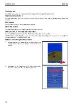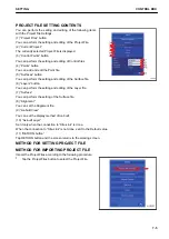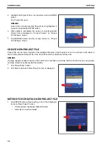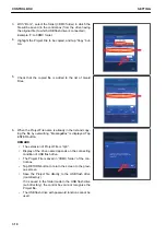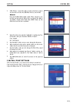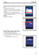
To use it, put a tick in the check box. By putting a tick, this Control Point becomes the vertical Control Point.
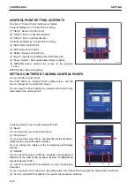
(6) “Measure...”:
You can obtain the Control Point Coordinates.
This is used to obtain the localized GNSS Coordinates.
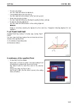
Tap “Measure...” button, and the screen changes to “Measure
Control Point” screen.
Select “Antenna Type” of GNSS antenna in order to obtain the
Control Point Coordinates.
You can input the value of the “Measured Height”.
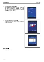
Check that the antenna is vertical and stationary, and tap EN-
TER button. The measurement of Coordinates starts.
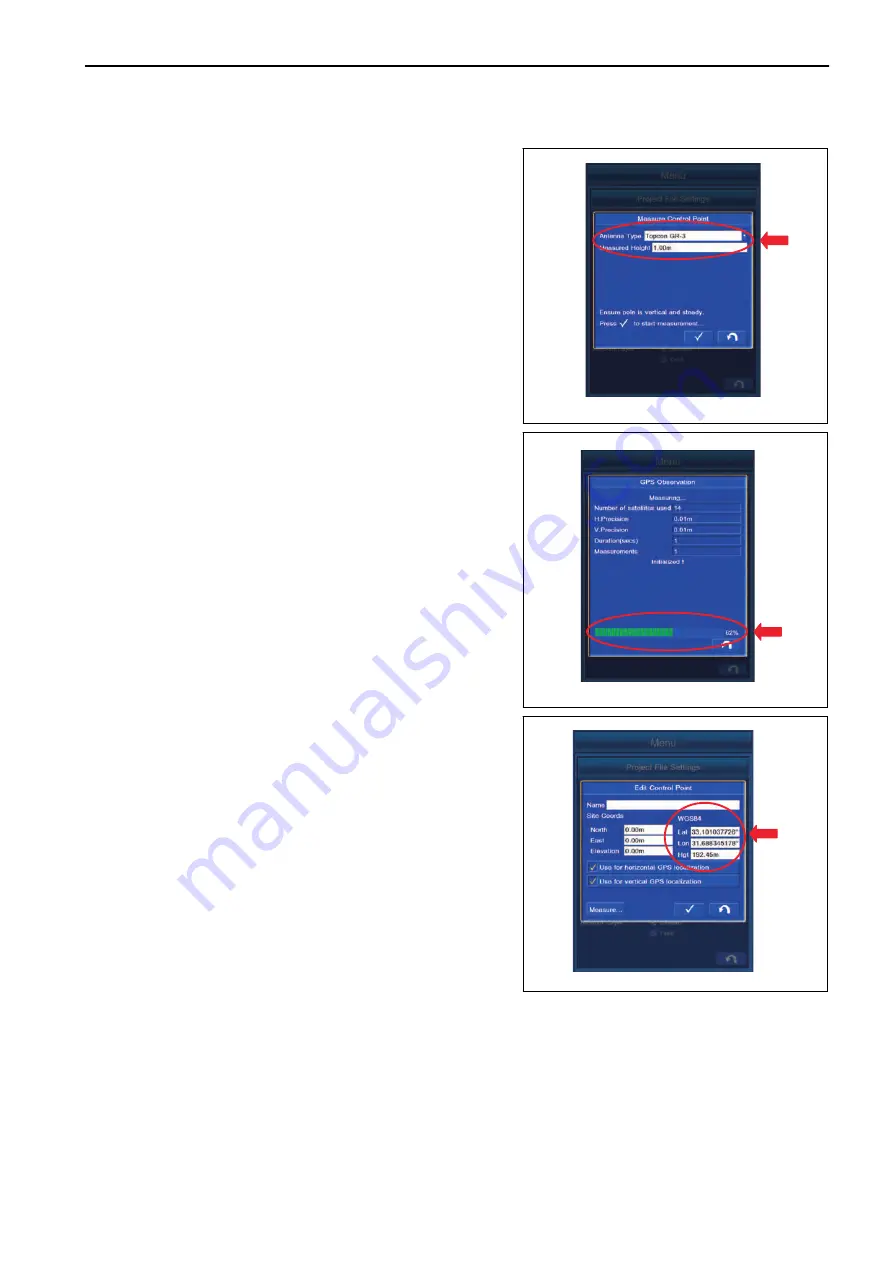
When the indicator shows 100%, the measurement is complet-
ed. After completion of measurement, the coordinates meas-
ured with world geodetic system WGS84 is displayed in “Con-
trol Point” screen.
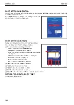
(7) ENTER button: You can save the setting.
(8) RETURN button: You can return the screen to the previous
screen.
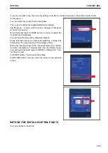
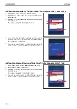
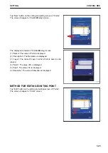
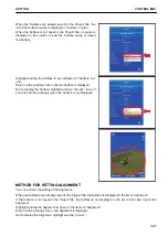
METHOD FOR EDITING CONTROL POINTS
You can edit the Control Point.
SETTING
CONTROL BOX
7-15
Summary of Contents for A31001
Page 12: ...LOCATION OF SAFETY LABELS Options are shown with marks in the figure SAFETY LABELS SAFETY 2 4...
Page 106: ......
Page 107: ...SPECIFICATIONS 5 1...
Page 110: ......
Page 116: ......
Page 117: ...SETTING 7 1...
Page 311: ...EXECUTIONS 8 1...
Page 376: ...PC360LCi 11 PC390LCi 11 HYDRAULIC EXCAVATOR Form No CEAM032703...


