CHANGING THE AUTHORIZED EQUIPMENT
219
6.2.2 CONNECTING THE HYDRAULIC CIRCUIT
WARNING
q
Before performing any operation on the hydraulic circuit, stop the engine and eliminate the residual
pressures from the equipment circuits by operating the controls more than once, then lock the safety
bars (see "3.3.5 pos. 1 - SAFETY BARS").
q
Immediately clean any area dirty with oil.
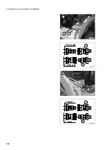
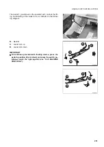
After the mechanical connection of equipment with indepen-
dent hydraulic circuit, make sure that the auxiliary kit control
pedal is in position A - flow interrupted - and introduce the
flexible pipes of the equipment connection in the unions (1)
and (2). See B,C and D
The rapid coupling must be in compliance with the ISO 8434-3
standard.
IMPORTANT
q
In case of doubts regarding the connection of the hy-
draulic circuit to the equipment, contact your Komatsu
Dealer
RWA36090
1" UNS
1" UNS
1
2
RWAA11790
1
2
B
RWAA12680
A
Summary of Contents for 37BF50111
Page 2: ......
Page 17: ...SAFETY AND ACCIDENT PREVENTION 15...
Page 19: ...SAFETY NOISE AND VIBRATION PLATES 17 RWA00010 RWA37020...
Page 21: ...SAFETY NOISE AND VIBRATION PLATES 19 RWA37040 RWA00010 RWA00020...
Page 53: ...THE MACHINE AND ITS OPERATIONS 51...
Page 62: ...GENERAL VIEWS 60 10 Left console switches 11 Right console switches RWAA9720 11 RWAA11260 10...
Page 154: ...152 PAGE INTENTIONALLY LEFT BLANK...
Page 155: ...MAINTENANCE 153...
Page 205: ...TECHNICAL SPECIFICATIONS 203...
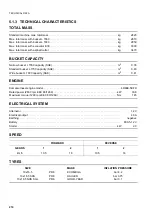
Page 213: ...TECHNICAL DATA 211 SOLID TYRES SIZE MAKE 10x16 5 AIR BOSS...
Page 214: ...212 PAGE INTENTIONALLY LEFT BLANK...
Page 215: ...AUTHORISED OPTIONAL EQUIPMENT 213...
Page 242: ...240 PAGE INTENTIONALLY LEFT BLANK...
Page 243: ......
Page 244: ...2004 KOMATSU UTILITY EUROPE S p A All Rights Reserved Printed in Europe...

