background image

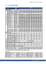
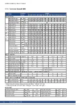
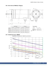
17.3 Technical Data AKMH3

Data

Symbol
[Unit]

AKMH

31C

31E

31H

32C

32E

32H

33C

33E

33H

Electrical data

Standstill torque*

M

0

[Nm]**

1.00

1.04

1.08

1.72

1.77

1.82

2.25

2.32

2.38

Standstill current

I

0rms

[A]**

1.29

2.76

5.59

1.30

2.56

4.92

1.27

2.20

4.78

max. Mains voltage

U

N

[VAC]

480

U

N

=

230V

Rated speed

n

n

[rpm]

2500

6000

8000

1500

3500

7000

1000

2000

5500

Rated torque*

M

n

[Nm]

0.95

0.86

0.76

1.66

1.57

1.13

2.22

2.20

1.64

Rated power

P

n

[kW]

0.25

0.54

0.64

0.26

0.57

0.83

0.23

0.46

0.94

U

N

=

400V

Rated speed

n

n

[rpm]

6000

8000

8000

3000

7000

8000

2000

4500

8000

Rated torque*

M

n

[Nm]

0.82

0.74

0.76

1.57

1.10

0.95

2.14

1.82

0.88

Rated power

P

n

[kW]

0.51

0.62

0.64

0.49

0.81

0.80

0.45

0.86

0.74

U

N

=

480V

Rated speed

n

n

[rpm]

6000

8000

8000

3500

8000

8000

2500

5000

8000

Rated torque*

M

n

[Nm]

0.82

0.74

0.76

1.52

0.92

0.95

2.09

1.72

0.88

Rated power

P

n

[kW]

0.51

0.62

0.64

0.56

0.77

0.80

0.55

0.90

0.74

Peak current

I

0max

[A]

6.90

15.0

29.3

7.2

14.1

27.5

7.4

12.9

28.1

Peak torque

M

0max

[Nm]

4.41

4.52

4.59

8.10

8.24

8.39

11.5

11.7

11.9

Torque constant

K

Trms

[Nm/A]

0.85

0.41

0.21

1.4

0.73

0.39

1.86

1.10

0.52

Voltage constant

K

Erms

[mVmin]

54.5

26.1

13.7

89.8

47.1

24.8

120

70.6

33.4

Winding resistance Ph-Ph

R

25

[

]

21.4

4.76

1.31

23.8

6.32

1.71

26.6

9.03

1.98

Winding inductance Ph-Ph L [mH]

37.5

8.6

2.4

46.5

12.8

3.53

53.6

18.5

4.1

Mechanical data

Rotor moment of inertia

J [kgcm²]

0.33

0.59

0.85

Pole number

8

8

8

Static friction torque

M

R

[Nm]

0.093

0.099

0.105

Thermal time constant

t

TH

[min]

24

32

40

Weight flange mounting**

G [kg]

4.1

5

5.9

Weight face mounting**

G [kg]

4.5

5.4

6.4

Radial load permitted

F

R

[N]

max. 200, (

# 63)

Axial load permitted

F

A

[N]

max. 600, (

# 63)

Derating depending on model options for M

0

and I

orms

(data evaluation in process)

Built-in brake

%

i.p.

i.p.

i.p.

Built-in Hiperface DSL

%

i.p.

i.p.

i.p.

Power cable acc. EN60204-1:2006 Table 6, Column B2

Minimum cross section

mm²

1

1

1

1

1

1

1

1

1

Fixed cable cross section

mm²

2.5

2.5

2.5

2.5

2.5

2.5

2.5

2.5

2.5

* Rated data with reference flange Aluminium 254mm * 254mm * 6.35mm
** cable weight adder (0.32 kg/m)

Brake data

Holding torque @ 120°C

M

BR

[Nm]

2.5

Release delay time

t

BRH

[ms]

25

Operating voltage

U

BR

[VDC]

24 ± 10 %

Engage delay time

t

BRL

[ms]

10

Electrical power

P

BR

[W]

10.1

Brake weight adder

G

BR

[kg]

0.7

Moment of inertia

J

BR

[kgcm²]

0.012

Typical backlash

[ °mech.]

0.46

AKMH Installation | Table of Contents

56

Kollmorgen | March 2014

Summary of Contents for AKMH2

Page 1: ...sch European Version CE region Designed to EHEDG standards Bewahren Sie alle Anleitungen w hrend der gesamten Nutzungsdauer des Produkts als Produktkomponente auf H ndigen Sie alle Anlei tungen k nfti...

Page 2: ...Dieses Dokument ist geistiges Eigentum von Kollmorgen Alle Rechte vorbehalten Kein Teil dieses Werkes darf in irgendeiner Form Fotokopie Mikrofilm oder in einem anderen Verfahren ohne schriftliche Ge...

Page 3: ...4 1 Allgemeine technische Daten 18 4 2 Standardausr stung 18 4 2 1 Schutzart 18 4 2 2 Isolierstoffklasse 18 4 2 3 Oberfl che 18 4 2 4 Wellenende 19 4 2 5 Schutzeinrichtung 19 4 2 6 Schwingg te 19 4 3...

Page 4: ...2 12 2 Standard features 42 12 2 1 Protection class 42 12 2 2 Insulation material class 42 12 2 3 Surface 42 12 2 4 Shaft end 43 12 2 5 Protective device 43 12 2 6 Vibration class 43 12 3 Hygienic des...

Page 5: ...es AKMH3 63 18 7 Dimensions AKMH4 Ax flanges 64 18 8 Dimensions AKMH4 Cx flanges 65 18 9 Radial axial forces AKMH4 65 18 10 Dimensions AKMH5 Ax flanges 66 18 11 Dimensions AKMH5 Cx flanges 67 18 12 Ra...

Page 6: ...rsiblen Verletzungen f hren wird Weist auf eine gef hrliche Situation hin die wenn sie nicht vermieden wird zum Tode oder zu schweren irreversiblen Verletzungen f hren kann Weist auf eine gef hrliche...

Page 7: ...llung Montage Inbetriebnahme und Betrieb von Motoren vertraut sind und ber die ihrer T tigkeit entsprechenden Mindestqualifikationen verf gen l Transport nur durch Personal mit Kenntnissen in der Beha...

Page 8: ...gef hrliche Spannungen Messen Sie zur Sicherheit die Spannung im Zwischenkreis und warten Sie bis die Spannung unter 60V abgesunken ist H ngende Lasten sichern Eingebaute Haltebremsen sind nicht funkt...

Page 9: ...Bauteile der Anlage in Betrieb genommen werden l Der in die Motorwicklungen eingebaute Thermoschutzsensor muss ausgewertet und ber wacht werden l Eingebaute Haltebremsen sind als Stillstandsbremsen a...

Page 10: ...bereich bestimmt sind Bei Einbau in Maschinen oder Anlagen ist die Aufnahme des bestimmungsgem en Betriebes solange untersagt bis festgestellt wurde dass die Masch ine oder Anlage den Bestimmungen der...

Page 11: ...agen muss Dies kann zum Ausfall des Motors oder zum Strom schlag f hren Verpackung l Kartonverpackung mit Instapak Aussch umung l Den Kunststoffanteil k nnen Sie an den Lieferanten zur ckgeben Motorty...

Page 12: ...ht weiterbetrieben werden die Lager m ssen erneuert werden vom Hersteller o Nach 20 000 Betriebsstunden unter Nennbedingungen Erneuern der Kugellager Motor an Hersteller schicken l ffnen der Motoren b...

Page 13: ...igungskit AKMH5 Ax Flanschmontage Cx Frontmontage MTG KIT AKMH6 IEC Befestigungskit AKMH6 Ax Flanschmontage Cx Frontmontage NEMA Befestigungssets sind im amerikanischen Selection Guide beschrieben ver...

Page 14: ...4 Typenschl ssel NEMA Flanschtypen sind im amerikanischen Selection Guide beschrieben verf gbar auf der Kollmorgen Website www kollmorgen com AKMH Installation Table of Contents 14 Kollmorgen March 20...

Page 15: ...uform IM B5 nach DIN EN 60034 7 Legen Sie zur Abdichtung den O Ring in die Flanschnut ein Frontmontage Flanschtypen Cx Dx Die Grundbauform f r Frontmontage ist die Bauform IM B14 nach DIN EN 60034 7 L...

Page 16: ...von kurz nach lang Innerhalb jeder Rotorl nge sind zahlreiche Wicklungsvarianten defi niert Ma zeichnungen finden Sie im Kapitel Dimension Drawings 60 3 4 4 Wicklungstyp Optionen Kollmorgen definiert...

Page 17: ...den Sprechen Sie hierzu mit unserem Kundendienst 3 4 8 Anschluss Optionen Das Hybridkabel beinhaltet Adern f r Leistung und Feedback und einen Schlauch zum Druck ausgleich des Innendrucks im Motor Kod...

Page 18: ...sdauer 20 000 Betriebsstunden Technische Daten der Motortypen finden Sie im Kapitel Technical Data 54 4 2 Standardausr stung 4 2 1 Schutzart Wellendichtung Option Flanschdichtung Schutzart K O Ring IP...

Page 19: ...mmen im Kapitel Dimension Drawings 60 Die zugelassenen Maximalwerte finden Sie in den technischen Daten Kupplung Als ideale spielfreie Kupplungselemente haben sich doppelkonische Spannzangen eventuell...

Page 20: ...r ist konform zu den europ ischen Hygienerichtlinien Anforderungen IP69K EHEDG i V Lebensmittel Nicht Lebensmittel O Ring erforderlich erforderlich FDA Schlauch erforderlich Wellendichtung erforderlic...

Page 21: ...ensdauer nur bei Einsatz der getesteten Reinigungsmittel geben Andere als die oben genannten Reinigungsmittel kann Kollmorgen auf Anfrage testen und gegebenenfalls freigeben 4 3 2 Reinigungsplan Empfo...

Page 22: ...temperatur Bei Umgebungstemperaturen ber 40 C sprechen Sie mit unserer Applikationsabteilung Sorgen Sie f r ausreichende W rmeabfuhr in der Umgebung und am Motorflansch l Flansch und Welle sind bei La...

Page 23: ...schraubt werden Flanschmontage A Durchgangsbohrungen im Flansch erm glichen Montage von der R ckseite mit Dichtungsschrauben Nur B5 Montage gem EN 60034 7 Frontmontage C Gewinde im Flansch erm glichen...

Page 24: ...Sie vor dem Langzeiteinsatz die Vertr glichkeit der verwendeten Reinigungsmittel mit dem Motorkabel Im Lebensmittelbereich muss die Schlauchoption f r das Kabel ver wendet werden 5 4 2 Schlauch Verdra...

Page 25: ...lten der Netzspannung gef hrliche Werte auf weisen Leistungsanschl sse k nnen Spannung f hren auch wenn sich der Motor nicht dreht Messen Sie die Spannung im Zwischenkreis und warten Sie bis die Spann...

Page 26: ...ss an AKD B P T M Servoverst rkern mit 230V Nennspannung AKD xzzz06 Typen m ssen die Aderendh lsen auf den Motorleistungsadern um ca 2 3 mm gek rzt werden 3 Achten Sie auf einwandfreie Erdung von Serv...

Page 27: ...stungsanschl sse k nnen Spannung f hren auch wenn sich der Motor nicht dreht Messen Sie die Spannung im Zwischenkreis und warten Sie bis die Spannung unter 60V abgesunken ist Die Oberfl chentemperatur...

Page 28: ...retende Auff lligkeiten im Regelverhalten haben meist ihre Ursache in fehlerhafter Parametrierung des Servoverst rkers Informieren Sie sich hierzu in der Dokumentation des Servoverst rkers und der Inb...

Page 29: ...von der Wicklung Der Spitzenstrom des verwendeten Servoverst rkers muss kleiner sein Drehmomentkonstante KTrms Nm A Die Drehmomentkonstante gibt an wie viel Drehmoment in Nm der Motor mit 1A Sinus Ef...

Page 30: ...Indicates a hazardous situation which if not avoided will result in death or serious injury Indicates a hazardous situation which if not avoided could result in death or serious injury Indicates a haz...

Page 31: ...transport installation assembly commissioning and operation of motors and who bring their relevant minimum qualifications to bear on their duties l Transport only by personnel with knowledge of handl...

Page 32: ...DC link voltage and wait until the volt age has fallen below 60V Secure hanging loads Built in holding brakes do not ensure functional safety Hanging loads vertical axes require an additional external...

Page 33: ...or machines and can only be commissioned and put into operation as integral components of such apparatus or machines l The thermal sensor which is integrated in the motor windings must be connected an...

Page 34: ...ant the motor must not be used until it has been established that the machine or equipment fulfills the require ments of the l EC Machinery Directive 2006 42 EC l EC EMC Directive 2004 108 EC l EC Low...

Page 35: ...to electrocution haz ard due to failure of electrical terminations Packaging l Cardboard packing with Instapak foam cushion l You can return the plastic portion to the supplier see Disposal Motor type...

Page 36: ...f any noises are heard stop the operation of the motor the bearings must be replaced by the manufacturer o After 20000 hours of normal operation replace all bearings after 20 000 hours of oper ation u...

Page 37: ...nt mounting MTG KIT AKMH6 IEC Mounting Hardware AKMH6 Ax flange Cx front mounting NEMA mounting kits are described in the US selection guide available from the Kollmorgen website www kollmorgen com 11...

Page 38: ...11 4 Model number description NEMA flanges are described in the US selection guide available from the Kollmorgen website www kollmorgen com AKMH Installation Table of Contents 38 Kollmorgen March 2014...

Page 39: ...ing is style IM B5 according to EN 60034 7 Mount the FDA approved o ring for flange sealing Face mounting flange types Cx Dx The basic style for face mounting is style IM B14 according to EN 60034 7 M...

Page 40: ...gs are defined Drawings can be found in chapter Dimension Drawings 60 11 4 4 Winding type options Kollmorgen defines windings with a single character A to Z from low currect to high current windings T...

Page 41: ...ort department 11 4 8 Connection options The hybrid cable combines power and feedback signals and is connected inside the motor The cable includes a tube for pressure compensation Codes K and T Cable...

Page 42: ...hours Technical data for every motor type can be found in chapter Technical Data from p xxx 12 2 Standard features 12 2 1 Protection class Shaft seal option Flange sealing Protection class K O Ring IP...

Page 43: ...Dimension Drawings 60 The maximum values at rated speed are listed at the technical data Coupling Double coned collets have proved to be ideal zero backlash coupling devices combined if required with...

Page 44: ...ending Food Grade Non Food Grade O Ring necessary necessary Cable tube necessary Shaft seal necessary necessary Application Area Foodstuffs and drinks industry no direct contact with unpacked foodstuf...

Page 45: ...r the motor s lifecycle if the tested cleansing agents are used Any cleansing agent other than those mentioned above can be tested by Koll morgen upon request and if appropriate be approved 12 3 2 Cle...

Page 46: ...mperatures above 40 C please consult our appli cations department beforehand Ensure that there is adequate heat transfer in the sur roundings and the motor flange l Motor flange and shaft are especial...

Page 47: ...e of the flange or from the front side Flange mount A Through bores allow mounting with sealed screws from rear side B5 mounting only according to EN 60034 7 Flange mount C Threads allow mounting with...

Page 48: ...ompatibility of the cable to cleaning solutions used in the application should be evaluated before subjecting the cable to long term exposure to chemicals Using the motor in food grade applications re...

Page 49: ...still present on the capacitors up to 10 minutes after switch off of the mains supply Even when the motor is not rotating control and power leads may be live Measure the DC link voltage and wait until...

Page 50: ...T M drive with 230V rated supply voltage AKD xzzz06 types then the ferrule tips supplied on motor power wires must be trimmed by approximately 2 to 3 mm 3 Ensure that there is proper earthing of the...

Page 51: ...s supply has been switched off Even when the motor is not rotating control and power leads may be live Measure the DC link voltage and wait until it has fallen below 60V The surface temperature of the...

Page 52: ...ties which show up in the control loop behaviour can usually be traced back to an error in the param eterization of the drive The documentation for the drive and the setup software provides infor mati...

Page 53: ...g The actual value is determined by the peak current of the drivewhich is used Torque constant KTrms Nm A The torque constant defines how much torque in Nm is produced by the motor with 1A r m s curre...

Page 54: ...ento di aderenza statica Par est tico de fricci n Thermal time constant Thermische Zeitkonstante Costante di tempo termica Constante t rmica de tiempo Weight standard Gewicht standard Peso standard Pe...

Page 55: ...0 36 Voltage constant KErms mVmin 19 5 39 20 4 33 8 27 17 6 40 8 32 4 23 4 Winding resistance Ph Ph R25 13 0 20 0 5 24 8 79 5 46 2 36 9 04 5 46 2 96 Winding inductance Ph Ph L mH 19 0 35 5 9 7 17 3 1...

Page 56: ...1 86 1 10 0 52 Voltage constant KErms mVmin 54 5 26 1 13 7 89 8 47 1 24 8 120 70 6 33 4 Winding resistance Ph Ph R25 21 4 4 76 1 31 23 8 6 32 1 71 26 6 9 03 1 98 Winding inductance Ph Ph L mH 37 5 8 6...

Page 57: ...23 5 Torque constant KTrms Nm A 1 34 0 71 0 37 2 4 1 26 0 59 0 43 1 72 0 89 0 42 2 04 1 06 0 59 Voltage constant KErms mVmin 86 3 45 6 23 7 154 80 9 38 3 27 5 111 57 4 27 5 132 68 0 37 8 Winding resis...

Page 58: ...e constant KTrms Nm A 1 72 0 8 0 41 2 79 1 44 0 75 0 66 1 75 0 99 0 60 2 57 1 13 0 74 Voltage constant KErms mVmin 110 51 3 26 6 179 92 7 48 3 42 4 112 63 9 38 4 166 72 9 47 3 Winding resistance R25 9...

Page 59: ...66 2 54 2 1 1 85 Voltage constant KErms mVmin 142 1 65 5 58 8 194 5 98 2 79 9 147 107 164 133 119 Winding resistance R25 3 320 0 757 0 587 3 45 0 957 0 627 1 43 0 767 1 35 1 07 0 747 Winding inductanc...

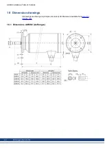
Page 60: ...nsion drawings All drawings are drawings in principle not scaled 3D Models are available from www kol lmorgen com 18 1 Dimensions AKMH2 Ax flanges AKMH Installation Table of Contents 60 Kollmorgen Mar...

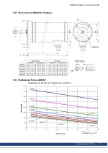
Page 61: ...18 2 Dimensions AKMH2 Cx flanges 18 3 Radial axial forces AKMH2 Radialkr fte am Wellenende Radial Force at shaft end AKMH Installation Table of Contents Kollmorgen March 2014 61...

Page 62: ...18 4 Dimensions AKMH3 Ax flanges AKMH Installation Table of Contents 62 Kollmorgen March 2014...

Page 63: ...18 5 Dimensions AKMH3 Cx flanges 18 6 Radial axial forces AKMH3 Radialkr fte am Wellenende Radial Force at shaft end AKMH Installation Table of Contents Kollmorgen March 2014 63...

Page 64: ...18 7 Dimensions AKMH4 Ax flanges AKMH Installation Table of Contents 64 Kollmorgen March 2014...

Page 65: ...18 8 Dimensions AKMH4 Cx flanges 18 9 Radial axial forces AKMH4 Radialkr fte am Wellenende Radial Force at shaft end AKMH Installation Table of Contents Kollmorgen March 2014 65...

Page 66: ...18 10 Dimensions AKMH5 Ax flanges AKMH Installation Table of Contents 66 Kollmorgen March 2014...

Page 67: ...18 11 Dimensions AKMH5 Cx flanges 18 12 Radial axial forces AKMH5 Radialkr fte am Wellenende Radial Force at shaft end AKMH Installation Table of Contents Kollmorgen March 2014 67...

Page 68: ...18 13 Dimensions AKMH6 Ax flanges AKMH Installation Table of Contents 68 Kollmorgen March 2014...

Page 69: ...18 14 Dimensions AKMH6 Cx flanges 18 15 Radial axial forces AKMH6 Radialkr fte am Wellenende Radial Force at shaft end AKMH Installation Table of Contents Kollmorgen March 2014 69...

Page 70: ...19 Approvals 19 1 Underwriters Laboratories Recognized for UL and Canada in File E61960 19 2 EC Declaration of Conformity AKMH Installation Table of Contents 70 Kollmorgen March 2014...

Page 71: ...19 3 Hygienic Standards Declaration of Conformity AKMH Installation Table of Contents Kollmorgen March 2014 71...

Page 72: ...a updated hints for machine builders hygienic standards fulfilled by AKMH CE Declaration and Conformity Hygienic Standards Conformity Declaration B 03 2014 Part number scheme updated typos corrected F...

Page 73: ...AKMH Installation Kollmorgen March 2014 73...

Page 74: ...74 Kollmorgen March 2014 AKMH Installation...

Page 75: ...marketplace advantage For assistance with your application needs visit www kollmorgen com or contact us at North America KOLLMORGEN 203A West Rock Road Radford VA 24141 USA Web www kollmorgen com Mail...

Reviews: