AKD PDMM User Guide | 10.2.3 Drive Status
The Disable Timeout Setting determines the amount of time the drive will follow the disable mode before it
deactivates the drive regardless of method chosen and alerts with an Emergency Timeout Fault.
All disable modes operate based on the type of disable command received. Any critical faults, hardware
disable, or STO disable immediately turn off the power stage, and the motor will coast or free fall, depend-
ing on how the motor is secured.
10.2.3 Drive Status
The
Drive Status
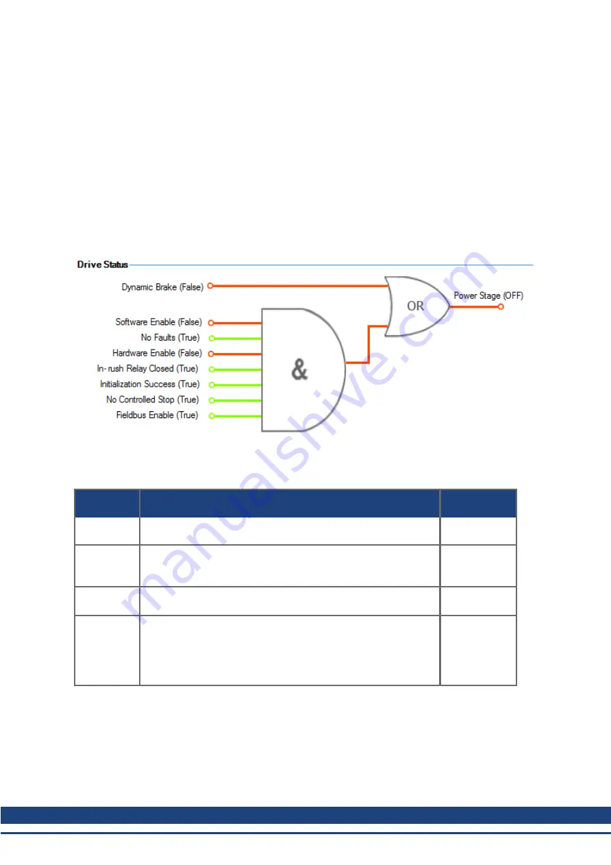
area is displayed below the settings area and includes a graphical representation of
drive active status with different sets of inputs. If the input or output is enabled, then it is shown in green; if
the input or output is disabled, then it is shown in red. The inputs to the OR and & (AND) gates identify
which conditions are true (green) or false (red) and follow the normal logic for & (AND) and OR gates. This
diagram is useful in finding which input may be preventing the drive from being enabled. Click
More
to see
the details of how the control stop is executed displayed both logically and graphically.
10.2.4 Controlled Stop
The Controlled Stop area displays values for parameters associated with controlled stop.
Button or
Dialog Box
Description
Parameter
Velocity
Threshold
Sets the velocity threshold for controlled stop process.
Velocity
Threshold
Timeout
Sets the velocity threshold, which is the time value for the drive
velocity to be within CS.VTHRESH before the drive disables
Deceleration
Sets the deceleration value for the controlled stop process.
Control stop
Input
Displays the list of digital inputs configured to controlled stop mode
separated by ','. When no controlled stop mode is configured, this
box displays the message:
No CS Input Configured
.
Configure Input
link will opens the Digital I/O screen where you
can configure the controlled stop mode.
10.2.5 More/Less Button
The
More
button reveals the status diagram for the controlled stop configuration. It also displays the block
diagram for the control stop. Two block diagrams available: one for a brake fitted and another for no brake.
Control stop status diagram
64
Kollmorgen™ | December 2012
Summary of Contents for AKD PDMM series
Page 25: ...This page intentionally left blank 25 Kollmorgen December 2012...
Page 32: ...This page intentionally left blank 32 Kollmorgen December 2012...
Page 52: ...This page intentionally left blank 52 Kollmorgen December 2012...
Page 101: ...AKD PDMM User Guide 12 3 6 2 Biquad Calculations 101 Kollmorgen December 2012...
Page 133: ...This page intentionally left blank 133 Kollmorgen December 2012...
Page 158: ...AKD PDMM User Guide 17 Connection Diagrams Kollmorgen December 2012 158...
Page 470: ...AKD PDMM User Guide 48 27 VL THRESH 1 Velocity Loop 470 Kollmorgen December 2012...
Page 511: ...This page intentionally left blank 511 Kollmorgen December 2012...
Page 513: ...This page intentionally left blank 513 Kollmorgen December 2012...


