background image

AVV-711 Quick Book

19

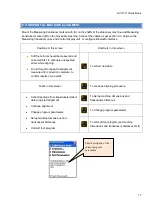
5.2 TO CHANGE PROGRAM PARAMETERS

To change program parameters press

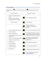
Cautions in this screen

Shortcuts in this screen

  Use biaxial live only where weak   shafts

coupling present

To select/reset use manual input

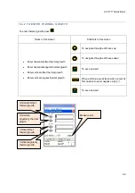
Tasks in this screen

To select/reset use manual angle

·

  Select to use manual input or transducers

data

·

  Select to use manual angle or

inclinometers embedded in transducers

·

  Select default display resolution

to 2 or 3 decimals

·

  Select default measure unit metric mm or

uk inches(mils)

·

  Select to enable biaxial live aligning(use

both Y and X coordinates) or use single Y
coordinates only(default)

To select/reset use 2 decimals resolution
(when reset it is 3 decimals)

To choose between measure unit metric mm
or uk inches(mils)

To select/reset biaxial live aligning mode

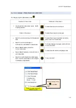
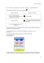
To save and exit

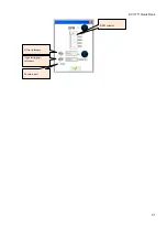
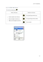
Filter(averaging) setup

use

 to confirm

input

Summary of Contents for AVV-711

Page 1: ...2013 KOHTECT AVV 711 LASER SHAFT ALIGNMENT SYSTEM OPERATING INSTRUCTIONS MANUAL...

Page 2: ...suring Units 13 3 4 Input of Dimensions 13 3 5 Rough Alignment Procedure 14 4 Getting Started 16 4 1 Common control keys consideration 16 4 2 To start AVV 711 16 5 Horizontal Machine Alignment 17 5 1...

Page 3: ...To setup machine dimensions and measure unit 48 8 2 To collect data and align 49 9 Dealing with file dialogs 50 General file dialog tasks 50 10 Setup program 52 10 1 To setup date and time 53 10 2 To...

Page 4: ...me 71 Screen overview 72 Coarse adjustment of the laser beam 73 Take review and replace measure 73 13 3 View and save result 74 13 4 Live move 75 14 Straightness program 76 Short explanation 76 Perfor...

Page 5: ...95 15 5 View and save result 98 reference plane modes 99 Define reference points 99 Result value modes 100 Enter tolerance 100 View statistics 101 16 Plumbline program 102 Short explanation 102 Perfo...

Page 6: ...measurements 110 17 3 View and save result 110 18 Squareness program 111 18 1 Main screen of the program 111 Basic workflow 112 18 2 Taking measurements 112 18 3 View and save result 113 Standards To...

Page 7: ...purpose before the mounting of equipment either block the power switch in the Off position or remove the safety fuses These precautionary rules must be followed until the measuring system is dismantle...

Page 8: ...olution 0 01 or 0 001 mm 1 or 0 1 mil 2 2 7 Measuring resolution 0 001mm 2 2 8 Electronic inclinometer resolution 0 1 degree 2 2 9 Power supply Rechargeable NiMH battery 2 2 10 Gross weight 7 5 kg 2 2...

Page 9: ...AC charger connecting cables CD ROM PC software USB PC communication cable Operating instructions manual in CD Carrying case with form inserted Top positions to be faced up while setting up both the t...

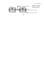
Page 10: ...nt of the correction planes basing on considerations of the convenience and technological effectiveness of moving of the movable M machine Stationary machine S in the process of eliminating of the axe...

Page 11: ...AVV 711 Quick Book 11 Fig 3...

Page 12: ...ion of the shafts with the S and M measuring transducer units with regard to the relative position of the S and M machines as in Fig 4 Fig 4 Fig 4 shows the view of S machine from the M end view at th...

Page 13: ...he Setup option Check and clean if necessary the surface of detectors and aperture of laser Use soft tampons moistened with alcohol for the cleaning Solvents must not be used Check and setup if necess...

Page 14: ...measuring transducer units S C distance between S and center of coupling S F1 distance between stationary detector S and the plane of alignment F1 3 5 ROUGH ALIGNMENT PROCEDURE Rough alignment should...

Page 15: ...using the laser adjustment screws adjust the beam half the travel in direction to the centre of the target Fig 8 Adjust the movable machine so that the laser beam hits the centers of both the targets...

Page 16: ...re designed with auto save For temporarily shut down your current work press until program exits to main menu of the device Data saved now device can be turned off 4 3 TO START AVV 711 After the booti...

Page 17: ...first to eliminate unexpected errors while aligning Do not forget to repeat misalignment measure after correction complete to confirm results of you work To collect new data Tasks in this screen To c...

Page 18: ...e lower than S F2 Navigate between length edit boxes up Tasks in this screen Navigate between length edit boxes down Enter stationary side transducer to center length Enter stationary side to movable...

Page 19: ...data Select to use manual angle or inclinometers embedded in transducers Select default display resolution to 2 or 3 decimals Select default measure unit metric mm or uk inches mils Select to enable...

Page 20: ...en auto sweep and manual modes Enter manual Ys Ym values if manual input is selected Enter manual angle if use manual angle is selected Choose measure units mm mils Navigate through collected readings...

Page 21: ...eep mode can be activated only at beginning of collect or after start from scratch option call must be no stored readings in other words Manual input and manual angle must both be deselected too State...

Page 22: ...must be present to advance to measure misalign step Presence of this image means extended Y values range used offset present Crossed image means auto sweep mode disabled Means auto sweep mode activat...

Page 23: ...but not less than 60 degrees When collect data completed press to start aligning Explanation of clock face Stored readings designated on clock face by green sectors and colored points around it Colore...

Page 24: ...ustment were performed Setup readings data offset for extend target range Target range extension can be in two different conditions first when beam s already out of target s or second when beams still...

Page 25: ...AVV 711 Quick Book 25 Press for switch to next step See figures beneath Wait until get ready counter disappears Press for switch to next step...

Page 26: ...S Fine adjust beams toward targets centers wait until get ready counter disappears and press to complete range extension Cancel should not be used if any adjustments were performed See figures beneath...

Page 27: ...l angle selected Choose 2 or 3 decimals display resolution Choose measure units mm mils Enter tolerances Enter thermal growth Save alignment result Load saved alignment Shims simulation To flange corr...

Page 28: ...ng checked box at plane header line means respective plane enabled to live update Otherwise live update for that plane not allowed Blinking shafts was turned error occurs when shafts position unexpect...

Page 29: ...d be in 6 or 12 o clock position Do shafts rotation as described in horizontal live alignment section Plane 6 12 should become enabled for live update Adjust the machine horizontal movement at feet pu...

Page 30: ...een Shortcuts in this screen Choose industry standard tolerances using RPM selection Manually enter desired tolerances To set tolerances by RPM To enter tolerances manually When set by RPM selected ch...

Page 31: ...AVV 711 Quick Book 31 RPM selector Offset tolerance Angularity gap tolerance Measure unit...

Page 32: ...nter vertical offset thermal growth Enter vertical angular thermal growth To navigate through edit boxes up To navigate through edit boxes down To save and exit When edit value press twice when cursor...

Page 33: ...im simulation press Tasks in this screen Shortcuts in this screen Enter front feet F1 shim thickness Enter rear feet F2 shim thickness Observe rest misalignment calculated To navigate through edit box...

Page 34: ...ure Save results see Dealing with file dialogs Setup machine dimensions first same as in horizontal alignment or skip this step press to go to sensors target screen When leave soft foot sensors target...

Page 35: ...uetooth interface Cautions in this screen Shortcuts in this screen Do not forget to repeat misalignment measure after correction complete to confirm results of you work To collect new data Tasks in th...

Page 36: ...or up Tasks in this screen Navigate between edit boxes and bolts selector down Enter stationary side transducer to center length Enter stationary side to movable side transducer length Enter stationar...

Page 37: ...n reset it is 3 decimals Select to use manual input or transducers data Allow use of manual angle only Select default display resolution to 2 or 3 decimals Select default measure unit metric mm or uk...

Page 38: ...p to 36 Choose between auto sweep and manual modes Enter manual Ys Ym values if manual input is selected Enter manual angle Choose measure units mm mils Navigate through collected readings Delete add...

Page 39: ...be activated only at beginning of collect or after start from scratch option call must be no stored readings in other words Manual input and manual angle must both be deselected too States and signs...

Page 40: ...esent Crossed image means auto sweep mode disabled Auto sweep not allowed for vertical machines Aligning type sign H horizontal V vertical flange machine Current reading index last reading index from...

Page 41: ...collect data completed press to start aligning Explanation of clock face Stored readings designated on clock face by green sectors and colored points around it Colored points have round shape by defau...

Page 42: ...n To shim simulation Observe calculated misalignment result Perform live aligning Freeze thaw live alignment Enter manual angle when use manual angle selected Choose 2 or 3 decimals display resolution...

Page 43: ...his happened Coupling side in red means current misalignment exceeds tolerances it should be in gray when misalignment within entered tolerances Blinking checked box at plane header line means respect...

Page 44: ...AVV 711 Quick Book 44 Misalign offset Misalign angularity gap Measure unit Beam position Angles Clock face with graphically showed angles Manual angle edit box will appear here when 4 pressed...

Page 45: ...s rotation as described in 9 3 plane alignment section Plane 6 12 should become enabled for live update Loosen moveable machine feet and start adjusting the movable machine position on 6 12 axis only...

Page 46: ...Manually enter desired tolerances To set tolerances by RPM To enter tolerances manually When set by RPM selected change RPM one step up When enter manually selected select offset tolerance edit box Wh...

Page 47: ...in cardan menu Cautions in this screen Shortcuts in this screen Soft foot errors should be measured and corrected first to eliminate unexpected errors while aligning Do not forget to repeat misalignme...

Page 48: ...s screen Shortcuts in this screen Navigate between length edit boxes up Tasks in this screen Navigate between length edit boxes down Enter stationary side to movable side transducer length Enter lengt...

Page 49: ...than 75 degrees Offset corrections are not applicable to cardan shaft alignment Therefore offset misalignment values does not displayed Standard tolerances are not applicable to cardan shaft alignmen...

Page 50: ...file Enter Edit file name to be saved Auto generate file name for file to be saved current date time When folders and files list selected navigate on this list When disk selection field selected selec...

Page 51: ...ion list When save dialog invoke auto name current date time feature Automatically generated file name placed into file name edit box If folder highlighted move one step down through folders hierarchy...

Page 52: ...th Select user language Observe firmware build version and some status information To setup date and time To setup power off time To setup view licenses for programs To setup transducers interface To...

Page 53: ...ss Tasks in this screen Shortcuts in this screen Setup Date and Time Move between fields left Move between fields right Increment current field value Decrement current field value Move between fields...

Page 54: ...n Shortcuts in this screen Setup power off time in seconds Note 1 to disable power off set value to zero or leave empty Note 2 When value lower than 30 seconds entered the field become yellow to indic...

Page 55: ...to vendor When vendor sends license file to you copy this file to the device My documents folder directly or save it to the SD card than insert SD card in to the socket on device To load license file...

Page 56: ...transducers interface Configure Bluetooth interface slave devices number To select Bluetooth interface To select serial interface When Bluetooth is selected To configure to use single Bluetooth slave...

Page 57: ...57 10 5 TO SELECT USER LANGUAGE To select user language press Tasks in this screen Shortcuts in this screen Change user language To navigate through available languages list To change and exit To exi...

Page 58: ...nc 4 5 needed to access the device Do not perform any file read write operations on the device while device accessed through USB in mass storage mode Tasks in this screen Shortcuts in this screen Chan...

Page 59: ...aligning report to PDF file To copy content of internal documents folder to the storage card To start Windows CE explorer staff only do not use 11 1 TO VIEW REPORTS EXPLORE ORGANIZE FILES AND FOLDERS...

Page 60: ...be careful When folders and files list selected create new folder To move between folders and files list and disk selection field When disk selection field selected drop down hide disk selection list...

Page 61: ...evice Move one step up through folders hierarchy When folders and files list selected delete file or folder be careful When folders and files list selected create new folder To move between folders an...

Page 62: ...n t need to change destination target disk SD card or My documents folder there are simple 2 clicks procedure to save report in pdf file present first press to select report file save dialog appears T...

Page 63: ...perform machine train alignment PERFORM MACHINE TRAIN ALIGNMENT To start program select Train from main menu and press Main screen of the program appeared 12 1 MAIN SCREEN OF THE PROGRAM SETUP TRAIN...

Page 64: ...program main screen To view alignment result To add machine to the left side of train To add machine to the right side of train To setup parameters Reserved do nothing To save alignment to file see De...

Page 65: ...t change program parameters procedure Press to collect misalignment data for current coupling Each coupling is measured in the same way as in the Horizontal machine alignment program The minimum adjac...

Page 66: ...To setup thermal growth NOTE thermal growth always applied to left side shaft of machine Overview misalignment results and feet correction values Enter tolerances for shaft Enter thermal growth for m...

Page 67: ...data not collected at all ______ Magenta colored shaft indicates stationary reference machine Current machine Machine currently choosen as stationary reference Current machine number No collected dat...

Page 68: ...RES CENTERLINE ALIGNMENT To start program select Bores centerline from main menu and press Main screen of the program appeared 13 1 MAIN SCREEN OF THE PROGRAM CONFIGURE PLANES AND CHANGE PARAMETERS Ca...

Page 69: ...o file see Dealing with file dialogs To load previously saved data from file see Dealing with file dialogs To select bore for set distance to next and enter diameter optional SCREEN OVERVIEW Orange co...

Page 70: ...cted plane Next step setup parameters if any Press parameters screen appears To change of use manual input press to change of use manual angle need for vertical chains press To change display units be...

Page 71: ...ct to transducers can vary regard to connection type wired or wireless from 2 to 30 40 seconds It is recommended to wait up to 10 seconds when wired connection is used and up to 50 seconds when wirele...

Page 72: ...sition indicator means beam out of target condition means data not ready wait for some time means connection to transducer not established tilt indicator Count of the total measures stored for Current...

Page 73: ...arget then repeat adjustment procedure Coarse adjustment should be performed only once TAKE REVIEW AND REPLACE MEASURE To take measure press Stored measure will be showed on the stored measures indica...

Page 74: ...number and reference point 2 number respectively Press for store number To clear reference point enter decimal point as value Best fit mode In the best fit mode result is the difference between calcul...

Page 75: ...s until blinking LIVE MOVE showed Move object toward zero result To stop live and take result after moving press Do not stop live while measure data not ready beam out of target or hourglass or connec...

Page 76: ...reen All required dimensions should be properly entered but you can edit them later if need measure data will not affected To start new task Tasks in this screen To enter number of points positions to...

Page 77: ...ect point for set distance SCREEN OVERVIEW Current splice number textbox and total splices visible only if more than one splice present The means first and alone splice Orange color mark selected dist...

Page 78: ...plice number textbox If splice number textbox displays sign this means the first splice and no other splices defined If all measurement points in all splices evenly positioned equal distances used pre...

Page 79: ...l data chosen in parameters To manually enter detector value H To toggle display units To call context menu To walk through points forward and backward CONNECTION TIME Time for connect to transducers...

Page 80: ...ent point detector values means data not ready Beam position indicator means beam out of target condition means data not ready wait for some time means connection to transducer not established tilt in...

Page 81: ...tely centre of the target of receiver Move receiver to the first measurement point Check that is appropriate point no splice no if any selected on the display If the laser beam is far from centre of t...

Page 82: ...d reference point 2 number respectively Press for store number To clear reference point enter decimal point as value Best fit mode In the best fit mode result is the difference between calculated best...

Page 83: ...d start measurement Place receiver at position of the overlapped point exactly Always verify that point no and splice no on the AVV 711 display reflects real receiver position See how pieces of object...

Page 84: ...iece and the 1 and 2 for the second one First piece of straightness position from no 1 to last point no 5 2 nd piece of straightness position with from point no 1 to no 6 but only no 1 and 2 selected...

Page 85: ...ve and take result after moving press Don t stop live while measure data not ready beam out of target or hourglass or connection error After live move stopped change point ability become available To...

Page 86: ...ure Plan the measurement and mark the points where the detector will be placed Level the laser within 0 5 mm 20 mils in both X and Y direction Start the Flatness program Use S or M unit as detector Th...

Page 87: ...AVV 711 Quick Book 87 To create new circular grid To change parameters To select menu item Resume task from last state Resume task from collect state directly...

Page 88: ...parameters press or select menu item and press To change which transducer used as receiver press To change display measure unit press To setup filter press enter averaging value then press to confirm...

Page 89: ...following modes form left to right and vice versa or from up to down and vice versa For switch off press For turn on left to right press For turn on down and up press Press to confirm selection and ex...

Page 90: ...Total length width or Column row interval Every time you edit total length or total width column interval or row interval respectively will be recalculated Every time you edit column interval or row i...

Page 91: ...and press Use keys to move between editable fields Enter number of rings circles from 2 to 10 Enter number of points per ring from 3 to 40 for standard grid and up to 50 points allowed for extended g...

Page 92: ...point belongs Edit row ring position radius Edit column position Insert remove row ring Insert remove column point To insert row ring Row will be inserted at bottom side outer ring from the selected...

Page 93: ...om selected point Insert column bottom side from selected Save to file Go to measure press means scrolling to descent row number is accessible number in red means scrolling to ascend row number is acc...

Page 94: ...tion you can directly go to the desired point instead of slowly selection moving process Go to feature can be used while in grid editing measurement and result view Press to call go to dialog In resul...

Page 95: ...se of surface cut off etc Cautions in this screen Shortcuts in this screen Before take next measure wait for data ready should not blinking hourglass To clear selected point Tasks in this screen Go to...

Page 96: ...cted point coordinates row column Detector X axis value Detector Y axis value Beam position indicator Transducer inclination When blinks means connect to transducers not established measured point emp...

Page 97: ...711 Quick Book 97 Circular grid measure screen Refer to taking measurements selected position angle selected point coordinates ring position selected ring diameter For up side angle 0 increased clockw...

Page 98: ...ance 50 Yellow color means warn relative to tolerance 100 Red color means bad relative to tolerance 100 The header of the screen shows point coordinates and result value The value depends on reference...

Page 99: ...de when best fit mode selected result is the difference between calculated best fit reference plane and the detector value DEFINE REFERENCE POINTS DEFINE ZERO POINT You can define clear reference poin...

Page 100: ...fted up relative to most below value to be non negative All negative values shifted down relative to most above value to be non positive ENTER TOLERANCE To enter tolerance press Enter desired value in...

Page 101: ...nce shows current tolerance The colored bar at the bottom of the screen shows error percents and count of points in this error level The colored levels defined as follow Blue value 10 of tolerance Lig...

Page 102: ...the measure by placing transmitter at the first position 12 o clock confirm position by enter angle manually digit only without Mark the measurement points on the shafts Store all measurement values f...

Page 103: ...ate modify overview points Setup parameters Enter dimensions Start measurement View results available when all measurements taken Save file Load saved file To set or clear all distances equal To enter...

Page 104: ...next position Repeat for each points except last Next step setup parameters if any Press parameters screen appears To change of use manual input press to change of use manual angle press NOTE manual a...

Page 105: ...ally enter detector value H To manually enter angle required for position confirmation To toggle display units To call context menu To take or replace measure To walk through points forward and backwa...

Page 106: ...detector values means data not ready Beam position indicator means beam out of target condition means data not ready wait for some time means connection to transducer not established tilt indicator bl...

Page 107: ...mber respectively Press for store number To clear reference point enter decimal point as value Best fit mode In the best fit mode result is the difference between calculated best fit reference line an...

Page 108: ...711 Quick Book 108 Ref points mode best fit mode Red means tolerance violation yellow means tolerance violation Y axis result 12 6 o clock X axis result 9 3 o clock distance number of points calculat...

Page 109: ...if need measure data will not affected To start new task or repeat alignment all data will be lost Tasks in this screen To enter number of points positions to measure Enter dimension Start measurement...

Page 110: ...s stored To exit from measure mode press To exit from spindle program press again For save result to file press See dealing with file dialogs Transmiter label position up here Blinking blue shows sele...

Page 111: ...transmitter at the common corner of surfaces Place detector M Unit by default at the first position Perform rough laser beam alignment if necessary 18 1 MAIN SCREEN OF THE PROGRAM Cautions in this scr...

Page 112: ...TAKING MEASUREMENTS Press to take measure Use keys to change selected point Press to return from measure After taking measurements for 1 move detector to 2 position and take measure Then rotate laser...

Page 113: ...urement result press To save to file press To return to program main screen from result screen press To enter tolerance press If calculated result is out of tolerance value the second surface displays...

Page 114: ...pling that can be used under condition only if existing in house standards or the machine or coupling OEM have not given any blinding values and must not be exceeded Speed rpm Good Acceptable Offset A...

Page 115: ...ay Unit 1 2 Measuring Transducer Unit 2 3 Brackets Fame 2 4 Chains assembly 2 5 Supporting Rods 4 6 Connecting Cable 2 7 AC Charger 220 230Volts 1 8 Tape Measure 2m 1 9 Carrying Case 1 10 Operating In...

Reviews: