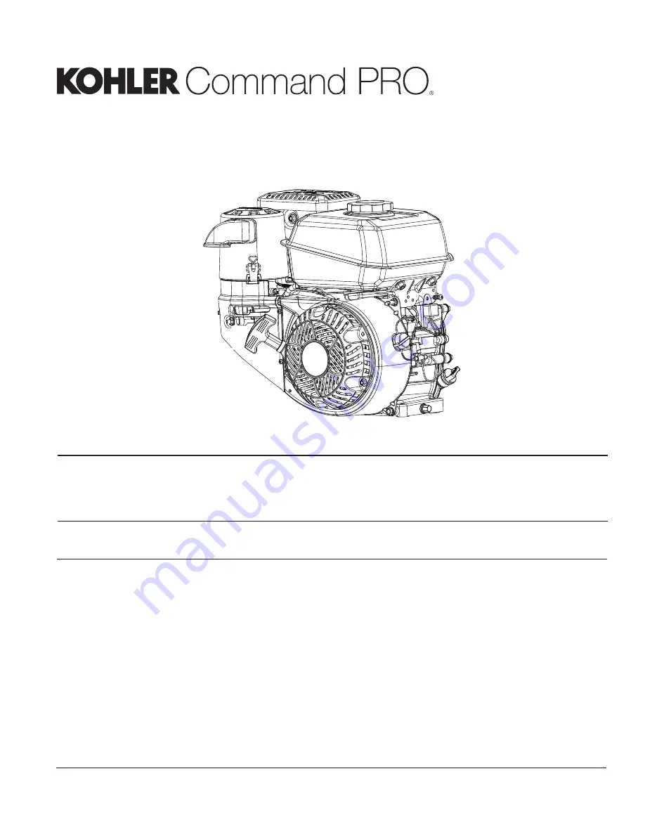
Kohler Command PRO CH260 Service Manual Download Page 1

1

17 690 01 Rev. F

KohlerEngines.com

CH260-CH440
Service Manual

2

Safety

3

Maintenance

5

Speci

fi

 cations

18

Tools and Aids

21

Troubleshooting

25

Air Cleaner/Intake

26

Fuel System 

30

Governor System

31

Lubrication System

32

Electrical System

39

Starter System

44

Disassembly/Inspection and Service

59

Reassembly

IMPORTANT:  Read all safety precautions and instructions carefully before operating equipment. Refer to operating 

instruction of equipment that this engine powers. 


Ensure engine is stopped and level before performing any maintenance or service.

Summary of Contents for Command PRO CH260

Page 1: ...tem 30 Governor System 31 Lubrication System 32 Electrical System 39 Starter System 44 Disassembly Inspection and Service 59 Reassembly IMPORTANT Read all safety precautions and instructions carefully before operating equipment Refer to operating instruction of equipment that this engine powers Ensure engine is stopped and level before performing any maintenance or service ...

Page 2: ...NING Accidental Starts can cause severe injury or death Disconnect and ground spark plug lead s before servicing Before working on engine or equipment disable engine as follows 1 Disconnect spark plug lead s 2 Disconnect negative battery cable from battery WARNING Hot Parts can cause severe burns Do not touch engine while operating or just after stopping Never operate engine with heat shields or g...

Page 3: ...leaner Intake Every 100 Hours or Annually Clean low profile air cleaner element Air Cleaner Intake Change oil Lubrication System Clean cooling areas Air Cleaner Intake Replace spark plug and set gap Electrical System Every 200 Hours Check and adjust valve clearance when engine is cold Reassembly Every 200 Hours Replace Quad Clean air cleaner element Air Cleaner Intake Every 300 Hours Replace low p...

Page 4: ...pproved and should NOT be used effects of old stale or contaminated fuel are not warrantable Fuel must meet these requirements Clean fresh unleaded gasoline Octane rating of 87 R M 2 or higher Research Octane Number RON 90 octane minimum Gasoline up to 10 ethyl alcohol 90 unleaded is acceptable Methyl Tertiary Butyl Ether MTBE and unleaded gasoline blend max 15 MTBE by volume are approved Do not a...

Page 5: ...5 Specifications 17 690 01 Rev F KohlerEngines com CH260 CH270 Engine Dimensions Dimensions in millimeters Inch equivalents shown in ...

Page 6: ...6 Specifications KohlerEngines com 17 690 01 Rev F CH260 CH270 Engine Dimensions Dimensions in millimeters Inch equivalents shown in ...

Page 7: ...7 Specifications 17 690 01 Rev F KohlerEngines com CH395 Engine Dimensions Dimensions in millimeters Inch equivalents shown in ...

Page 8: ...8 Specifications KohlerEngines com 17 690 01 Rev F CH395 Engine Dimensions Dimensions in millimeters Inch equivalents shown in ...

Page 9: ...9 Specifications 17 690 01 Rev F KohlerEngines com CH440 Engine Dimensions Dimensions in millimeters Inch equivalents shown in ...

Page 10: ...10 Specifications KohlerEngines com 17 690 01 Rev F CH440 Engine Dimensions Dimensions in millimeters Inch equivalents shown in ...

Page 11: ...e of Operation full oil level 4 25 TORQUE SPECIFICATIONS3 5 CH260 CH270 CH395 CH440 Air Cleaner Quad Clean Air Cleaner Base Mounting Screw 8 0 N m 71 in lb Low Profile Air Cleaner Base Mounting Screw 6 7 N m 59 in lb Blower Housing and Sheet Metal M6 Screw 10 N m 89 in lb M6 Nut 8 0 N m 71 in lb Carburetor Stud 10 N m 89 in lb Primary Nut 8 N m 71 in lb Intake Cover Nut 4 N m 35 in lb Intake Cover...

Page 12: ...lywheel Retaining Nut 74 N m 655 in lb 113 N m 1000 in lb Fuel Tank Mounting Nut 24 N m 212 in lb Mounting Screw 24 N m 212 in lb Inlet Fitting 1 5 N m 13 in lb Governor Lever Nut 12 N m 106 in lb Throttle Control Lever Nut 9 N m 80 in lb Ignition Spark Plug 27 N m 20 ft lb Module Fastener 10 N m 89 in lb Oil Sentry Float Switch Screw 8 N m 71 in lb Oil Sentry Module Screw 3 5 N m 31 in lb Oil Sen...

Page 13: ...it 27 533 mm 1 084 in 32 154 mm 1 266 in 32 032 mm 1 261 in Exhaust New 27 861 mm 1 097 in 32 12 mm 1 265 in 32 506 mm 1 280 in Max Wear Limit 27 607 mm 1 087 in 31 866 mm 1 255 in 32 252 mm 1 270 in Connecting Rod Crankpin End I D 21 C 70 F New 30 020 30 030 mm 1 1819 1 1823 in 33 020 33 030 mm 1 3000 1 3004 in 37 020 37 030 mm 1 4575 1 4579 in Max Wear Limit 30 106 mm 1 185 in 33 07 mm 1 302 in ...

Page 14: ...n Width 25 02 25 08 mm 0 9850 0 9874 in 30 30 30 36 mm 1 1930 1 1953 in 28 30 28 36 mm 1 1142 1 1165 in Runout either end 0 025 mm 0 001 in Main Bearing I D Crankcase Closure Plate New installed 24 992 25 000 mm 0 9839 0 9842 in 29 990 30 000 mm 1 1807 1 1811 in 34 988 35 000 mm 1 3775 1 3779 in Cylinder Bore Bore I D New 70 020 70 035 mm 2 7570 2 7573 in 78 000 78 015 mm 3 0709 3 0714 in 89 000 8...

Page 15: ...00 mm 0 010 0 016 in Used Bore Max 1 00 mm 0 039 in Center Compression Ring End Gap New Bore 0 325 0 400 mm 0 013 0 016 in 0 650 0 800 mm 0 026 0 032 in 0 640 0 800 mm 0 025 0 032 in Used Bore Max 1 00 mm 0 039 in 1 50 mm 0 059 in Oil Control Ring to Groove Side Clearance 0 05 0 19 mm 0 0019 0 0075 in 0 09 0 15 mm 0 0035 0 0059 in Piston Thrust Face O D New 69 975 69 995 mm 2 755 2 756 in 7 77 955...

Page 16: ...14 in 6 55 mm 0 258 in Max Wear Limit 5 28 mm 0 208 in 6 41 mm 0 252 in Intake Valve Stem to Guide New 0 024 0 039 mm 0 0009 0 0015 in 0 025 0 055 mm 0 0010 0 0022 in Max Wear Limit 0 10 mm 0 0039 in 0 13 mm 0 0051 in 0 14 mm 0 0055 in Exhaust Valve Stem to Guide New 0 098 0 112 mm 0 0038 0 0044 in 0 040 0 070 mm 0 0016 0 0028 in Max Wear Limit 0 12 mm 0 0047 in 0 10 mm 0 0039 in 0 11 mm 0 0043 in...

Page 17: ... English Fastener Torque Recommendations for Standard Applications Bolts Screws Nuts and Fasteners Assembled Into Cast Iron or Steel Grade 2 or 5 Fasteners Into Aluminum Size Grade 2 Grade 5 Grade 8 Tightening Torque N m in lb 20 8 32 2 3 20 2 8 25 2 3 20 10 24 3 6 32 4 5 40 3 6 32 10 32 3 6 32 4 5 40 1 4 20 7 9 70 13 0 115 18 7 165 7 9 70 1 4 28 9 6 85 15 8 140 22 6 200 5 16 18 17 0 150 28 3 250 ...

Page 18: ...3 Dealer Tool Kit Domestic Complete kit of Kohler required tools Components of 25 761 39 S Ignition System Tester Cylinder Leakdown Tester Oil Pressure Test Kit Rectifier Regulator Tester 120 V AC 60Hz Kohler 25 761 39 S Kohler 25 455 01 S Kohler 25 761 05 S Kohler 25 761 06 S Kohler 25 761 20 S Dealer Tool Kit International Complete kit of Kohler required tools Components of 25 761 42 S Ignition ...

Page 19: ...ent available Starter Brush Holding Tool Solenoid Shift SE Tools KLR 82411 SE Tools KLR 82416 Triad OHC Timing Tool Set For holding cam gears and crankshaft in timed position while installing timing belt Kohler 28 761 01 S Valve Guide Reamer K and M Series For properly sizing valve guides after installation Design Technology Inc DTI K828 Valve Guide Reamer O S Command Series For reaming worn valve...

Page 20: ...ring gear teeth Bosses will lock tool and flywheel in position for loosening tightening or removing with a puller A spanner wrench to lift rocker arms or turn crankshaft may be made out of an old junk connecting rod 1 Find a used connecting rod from a 10 HP or larger engine Remove and discard rod cap 2 Remove studs of a Posi Lock rod or grind off aligning steps of a Command rod so joint surface is...

Page 21: ...re to check simple causes which at first may seem too obvious to be considered For example a starting problem could be caused by an empty fuel tank Some general common causes of engine troubles are listed below and vary by engine specification Use these to locate causing factors Engine Will Not Crank Battery is discharged Faulty electric starter or solenoid Faulty key switch or ignition switch Int...

Page 22: ... indications of improper fit and seal Check air cleaner element Look for holes tears cracked or damaged sealing surfaces or other damage that could allow unfiltered air into engine A dirty or clogged element could indicate insufficient or improper maintenance Check carburetor throat for dirt Dirt in throat is further indication that air cleaner was not functioning properly Check if oil level is wi...

Page 23: ...is closed 2 Start engine and run no load high speed 3 Open clamp and note water level in tube Level in engine side should be a minimum of 10 2 cm 4 in above level in open side If level in engine side is less than specified low no vacuum or level in engine side is lower than level in open side pressure check for conditions in table below 4 Close pinch clamp before stopping engine To test crankcase ...

Page 24: ...ft Install a 3 8 in breaker bar into hole slot of holding tool so it is perpendicular to both holding tool and crankshaft PTO If flywheel end is more accessible use a breaker bar and socket on flywheel nut screw to hold it in position An assistant may be needed to hold breaker bar during testing If engine is mounted in a piece of equipment it may be possible to hold it by clamping or wedging a dri...

Page 25: ... engine oil squeeze out excess oil 4 Reinstall precleaner over paper element Paper Element 1 Separate precleaner from element service precleaner and replace paper element 2 Install new paper element on base install precleaner over paper element Position air cleaner cover for normal operation sun decal out or cold weather operation snowflake decal out place latches under tabs on base lift up bails ...

Page 26: ...f necessary New screen must be located on pick up tube 7 Place O ring on screen followed by fuel valve cup Rotate fuel valve cup until it is finger tight Turn with a wrench 1 2 to 3 4 turn 8 Turn fuel valve to ON position and check for leaks If fuel valve cup leaks repeat step 7 9 Reinstall carburetor cover panel using hardware removed in step 2 to secure FUEL SYSTEM TESTS When engine starts hard ...

Page 27: ...es are equipped with a fixed main jet carburetor Carburetor is designed to deliver correct fuel to air mixture to engine under all operating conditions Idle mixture is set at factory and cannot be adjusted Troubleshooting Checklist When engine starts hard runs rough or stalls at low idle speed check these areas before adjusting or disassembling carburetor 1 Make sure fuel tank is filled with clean...

Page 28: ...ses buoyant force of float will again overcome fuel pressure rising to predetermined setting and stop flow Slow and Mid Range At low speeds engine operates only on slow circuit As a metered amount of air is drawn through slow air bleed jets fuel is drawn through main jet and further metered through slow jet Air and fuel are mixed in body of slow jet and exit to idle progression transfer port chamb...

Page 29: ...and operated below 1219 meters 4000 ft High Idle Speed RPM Adjustment A A High Idle Speed Adjusting Stop Screw NOTE High idle speed is also specified by equipment manufacturer Set according to recommendations High idle speed for basic engines is 3600 RPM 150 RPM 1 Set high idle speed by turning high idle speed adjusting stop screw in or out Do not exceed 3750 RPM Carburetor Servicing WARNING Accid...

Page 30: ...y is rotating Force applied by regulating pin against cross shaft tends to close throttle plate Governor spring tension and force applied by regulating pin balance each other during operation to maintain engine speed When load is applied and engine speed and governor gear speed decreases governor spring tension moves governor arm to open throttle plate wider This allows more fuel into engine incre...

Page 31: ... be up to point of overflowing filler neck 3 If oil is low add oil up to point of overflowing filler neck 4 Reinstall dipstick or oil fill plug and tighten securely CHANGE OIL Change oil while engine is warm 1 Clean area around oil fill plug dipstick and drain plug 2 Remove drain plug and oil fill plug dipstick Drain oil completely 3 Reinstall drain plug Torque to 18 N m 13 ft lb 4 Fill crankcase ...

Page 32: ...re feeler gauge Adjust gap to 0 76 mm 0 03 in 2 Install plug into cylinder head 3 Torque plug to 27 N m 20 ft lb Inspection Inspect each spark plug as it is removed from cylinder head Deposits on tip are an indication of general condition of piston rings valves and carburetor Normal and fouled plugs are shown in following photos Normal Plug taken from an engine operating under normal conditions wi...

Page 33: ...rminal J Lamination K Kill Terminal These engines are equipped with a dependable magneto breakerless ignition In such a system electrical energy is generated by cutting of magnetic flux lines generated from ignition magnet on engine flywheel via prescribed air gap as it passes ignition module This energy is transferred through ignition module laminations and is then converted in module electronics...

Page 34: ... control module for any other results 5 Set an ohmmeter to Rx1 scale and zero meter Connect one ohmmeter lead to Oil Sentry float switch lead yellow with green sleeve and touch other lead to a bare spot on crankcase ground Drain oil from crankcase and repeat test With oil at proper level no continuity should have been indicated After oil was drained continuity should have been indicated Condition ...

Page 35: ...d in good condition Disconnect both battery cables before doing electrical welding on equipment powered by engine Also disconnect other electrical accessories in common ground with engine Prevent stator AC leads from touching or shorting while engine is running This could damage stator Most engines are equipped with a 3 4 10 or 18 amp regulated battery charging system 3 4 10 18 Amp Regulated Charg...

Page 36: ...90 01 Rev F Wiring Diagram 3 4 Amp Charging System Rectified Only B I F D C G J E A H K A Diode B Stator C Ignition Module D Spark Plug E Oil Float Switch F Oil Control Module G Key Switch H Starter Motor I Relay J Battery Fuse K 12 Volt Battery ...

Page 37: ...eads Connect an AC voltmeter across stator leads female terminals With engine running at 3600 RPM measure AC output from stator Condition Conclusion Voltage is 20 0 volts or more Stator is OK Rectifier regulator is faulty replace Voltage is less than 20 0 volts Stator is probably faulty and should be replaced Test stator further using an ohmmeter step 3 3 With engine stopped measure resistance fro...

Page 38: ...iring Diagram 10 18 Amp Charging System with Rectifier Regulator A I F D G J E B C H K A Rectifier Regulator B Stator C Ignition Module D Spark Plug E Oil Float Switch F Oil Control Module G Key Switch H Starter Motor I Relay J Battery Fuse K 12 Volt Battery ...

Page 39: ... Battery Check specific gravity of battery If low recharge or replace battery as necessary Wiring Check for corroded connections poor ground connection Transmission or Engine Make sure clutch or transmission is disengaged or placed in neutral This is especially important on equipment with hydrostatic drive Transmission must be exactly in neutral to prevent resistance which could keep engine from s...

Page 40: ...n 3 4 ohms or an open circuit is indicated infinity ohms Relay is faulty and must be replaced b With ohmmeter still on Rx1 scale connect leads to two large post terminals Meter should indicate an open circuit infinity ohms no continuity c Leave ohmmeter leads connected to large terminals Connect a jumper lead from positive terminal of battery to terminal of blue relay lead Connect another jumper l...

Page 41: ...E If access is available to remove screws 4 and separate drive end from motor gear end starter removal is not necessary If access is not available remove starter assembly from engine 1 Disconnect all lead wires from starter Note location of each for reassembly 2 Move square boot to access and remove brush lead connector wire screw 3 Remove 4 screws and separate starter 4 Remove drive assembly and ...

Page 42: ...arefully follow instructions in Retractable Starter for relieving spring tension Uncoiling Spring can cause severe injury Wear safety goggles or face protection when servicing retractable starter Retractable Starter Components A B C D F G H I E CH270 CH395 J H A Center Screw B Drive Plate C Friction Spring D Drive Pawl Dogs E Drive Pawl Springs F Pulley G Recoil Spring H Starter Rope I Starter Han...

Page 43: ...pproximately 12 in from free end of rope Hold pulley firmly and allow it to rotate slowly until slipknot reaches guide bushing of housing 11 Insert starter rope through starter handle and tie a double left hand knot at end of starter rope Insert knot into hole in handle 12 Untie slip knot and pull on starter handle until starter rope is fully extended Slowly retract starter rope into starter assem...

Page 44: ...Quad Clean Element Precleaner F Quad Clean Base G Carburetor Shroud H Fuel Tank I Fuel Line J CH260 CH270 Muffler Assembly K Low Profile Air Cleaner WARNING Before working on engine or equipment disable engine as follows 1 Disconnect spark plug lead s 2 Disconnect negative battery cable from battery Accidental Starts can cause severe injury or death Disconnect and ground spark plug lead s before s...

Page 45: ...ust flange and muffler bracket 2 Remove muffler assembly from exhaust outlet 3 Remove exhaust gasket from outlet Remove Air Cleaner Assembly Remove air cleaner components from air cleaner base Refer to Air Cleaner Intake Remove Quad Clean Base Remove air cleaner base from engine as follows 1 Remove nuts and screws securing carburetor shroud to engine 2 Remove shroud 3 Remove screw and nuts securin...

Page 46: ...Rev F CH260 CH270 Blower Housing Control Panel Components A C G H I F D E J K B A Retractable Starter B Blower Housing C Lower Shield D Carburetor E Dampening Spring F Throttle Linkage G Governor Lever H Hex Flange Nut I Governor Spring J Throttle Lever K Upper Shield ...

Page 47: ...ing Control Panel Components B E G J I A D C F K H M N G L A Retractable Starter B Blower Housing C Lower Shield D Electric Starter E Upper Shield F Carburetor G Fuel Brackets H Throttle Lever I Pivot Lever J Governor Spring K Dampening Spring L Throttle Linkage M Governor Lever N Hex Flange Nut ...

Page 48: ...g from throttle lever Disconnect throttle link and dampening spring from carburetor Remove carburetor carburetor gasket insulator and insulator gasket from studs Remove Retractable Starter Remove screws securing retractable starter to blower housing Remove starter Remove Blower Housing and Shields 1 Remove screws and nuts CH260 and CH270 only securing blower housing 2 Remove blower housing 3 Remov...

Page 49: ...on may be symptoms of faulty valves Although these symptoms could also be attributed to worn rings remove and check valves first After removal clean valve heads faces and stems with a power wire brush Then carefully inspect each valve for defects such as warped head excessive corrosion or worn stem end Replace valves found to be in bad condition Valve Guides If a valve guide is worn beyond specifi...

Page 50: ...ameter 30 875 31 125 mm 1 2156 1 2254 in 26 875 27 125 mm 1 0581 1 0679 in B Valve Length 85 34 85 54 mm 3 3598 3 3677 in 85 19 84 99 mm 3 3461 3 3539 in C Stem Diameter 6 560 6 575 mm 0 2583 0 2589 in 6 560 6 575 mm 0 2583 0 2589 in D Face Seat Width Maximum 1 5 mm 0 059 in 1 5 mm 0 059 in E Face Seat Angle 89 5 90 5 89 5 90 5 CH440 Valve Specifications Item Dimension Intake Exhaust A Head Diamet...

Page 51: ...H270 only on right side of flywheel required for use of puller in next step 4 Remove flywheel from crankshaft using a suitable puller 5 Remove flywheel key from crankshaft keyway Inspection Inspect flywheel for cracks and flywheel keyway for damage Replace flywheel if it is cracked Replace flywheel crankshaft and key if flywheel key is sheared or keyway is damaged Remove Stator if equipped 1 Remov...

Page 52: ...ure Plate Oil Seal B Closure Plate C Closure Plate Bearing D Camshaft E Crankshaft F Piston Pin Retainer G Piston Pin H Piston I Connecting Rod End Cap J Connecting Rod K Piston Ring Set L Governor Cup M Governor Washer N Governor Shaft O Governor Gear P Oil Sentry Float Switch Q Tappet R Oil Sentry Wire S Crankcase Bearing T Crankcase U Governor Cross Shaft V Crankcase Oil Seal ...

Page 53: ...sure Plate Bearing D Closure Plate Balance Shaft Bearing E Balance Shaft F Governor Shaft G Governor Washer H Governor Gear I Governor Cup J Crankshaft K Connector Rod End Cap L Connector Rod M Piston Pin Retainer N Piston Pin O Piston P Piston Ring Set Q Camshaft R Oil Sentry Float Switch S Oil Sentry Wire T Tappet U Crankcase Balance Shaft Bearing V Crankcase Bearing W Crankcase X Governor Cross...

Page 54: ...m 1 265 in 31 866 mm 1 255 in CH440 Cam Lobe INTAKE 32 286 mm 1 271 in 32 032 mm 1 261 in EXHAUST 32 506 mm 1 280 in 32 252 mm 1 270 in Remove Closure Plate NOTE Do not pry on gasket surface of crankcase or closure plate as this can cause damage and leakage 1 Remove screws securing closure plate to crankcase 2 Remove closure plate gasket and dowel pins if required from crankcase 3 Remove shims fro...

Page 55: ...25 mm 0 010 in undersized rods have an identification marking on lower end of rod shank Always refer to appropriate parts information to ensure correct replacements are used Piston and Rings Inspection Scuffing and scoring of pistons and cylinder walls occurs when internal engine temperatures approach welding point of piston Temperatures high enough to do this are created by friction which is usua...

Page 56: ...Gap B Bottom Oil Rail Gap C Oil Ring Expander Gap D Top Oil Rail Gap E Top Ring Gap NOTE Rings must be installed correctly Install bottom oil control ring first and top compression ring last Use a piston ring expander to install rings 1 Oil control ring bottom groove Install expander and then rails Make sure ends of expander are not overlapped 2 Middle compression ring center groove Install center...

Page 57: ...If governor gear shaft is bent or damaged remove it by pulling straight out 3 Remove hitch pin and washer from governor cross shaft 4 Remove cross shaft from inside crankcase Inspection Inspect governor gear teeth Replace gear if it is worn chipped or if any teeth are missing Inspect governor weights They should move freely in governor gear Remove Crankcase and Closure Plate Seals and Bearings NOT...

Page 58: ...micrometer telescoping gauge or bore gauge to take measurements These measurements should be taken at 3 locations in cylinder at top middle and bottom Two measurements should be taken perpendicular to each other at each location Clean Cylinder Bore After Honing Proper cleaning of cylinder walls following boring and or honing is very critical to a successful overhaul Machining grit left in cylinder...

Page 59: ...l Seal B Closure Plate C Closure Plate Bearing D Camshaft E Crankshaft F Piston Pin Retainer G Piston Pin H Piston I Connecting Rod End Cap J Connecting Rod K Piston Ring Set L Governor Cup M Governor Washer N Governor Shaft O Governor Gear P Oil Sentry Float Switch Q Tappet R Oil Sentry Wire S Crankcase Bearing T Crankcase U Governor Cross Shaft V Crankcase Oil Seal ...

Page 60: ...earing D Closure Plate Balance Shaft Bearing E Balance Shaft F Governor Shaft G Governor Washer H Governor Gear I Governor Cup J Crankshaft K Connector Rod End Cap L Connector Rod M Piston Pin Retainer N Piston Pin O Piston P Piston Ring Set Q Camshaft R Oil Sentry Float Switch S Oil Sentry Wire T Tappet U Crankcase Balance Shaft Bearing V Crankcase Bearing W Crankcase X Governor Cross Shaft Y Cra...

Page 61: ...surface CH440 8 2 mm 0 323 in from outer surface 4 Using an appropriate seal driver install oil seal into crankcase to depth specified below Install to a depth of CH260 CH270 CH440 0 0 1 0 mm 0 0 0 039 in from outer surface CH395 2 0 mm 0 079 in from outer surface 5 Apply a light coating of lithium grease to seal lips after installing Install Governor Assembly CH260 CH270 Governor Details A B C E ...

Page 62: ...ernor cross shaft and slide shaft up through inside of crankcase 4 Install second flat washer onto shaft Position shaft so flat index end of shaft faces left 9 o clock position and insert hitch pin from PTO side CH440 Governor Details B A C H G D E F K I J L A Closure Plate Sealing Surface B Governor Gear Shaft C Height D Pin Rim E Ring F Weights G Governor Gear H Thrust Washer I Washer J Hitch Pi...

Page 63: ...k position Install camshaft into crankcase aligning timing marks on two gears 4 Install original shims on crankshaft and camshaft Install Closure Plate CH260 CH270 Torque Sequence 1 2 3 4 5 6 4 Pull governor gear up until it makes contact with ring then place pin in cup retaining rim with weights 5 Push pin down snapping ring into shaft groove 6 Pull up slightly on governor gear to ensure assembly...

Page 64: ...Nut B Drive Cup C Flywheel Fan D Ignition Module E Flywheel F Stator G Flywheel Shield H Torque Sequence Install Stator If Equipped 1 Position stator aligning mounting holes so leads are in 3 o clock position 2 Install and torque screws to 10 N m 89 in lb in sequence of 1 2 3 4 and then torque 1 again 3 Route stator leads along crankcase and out notch on side 4 Position bracket over stator leads a...

Page 65: ... Install Ignition Module NOTE Ensure ignition module is correctly oriented 1 Turn flywheel so magnet is away from location where ignition module will be installed 2 Install ignition module loosely to bosses with screws Move module as far away from flywheel as possible then tighten screws just enough to hold it in position 3 Rotate flywheel until magnet is under one leg of ignition module 4 Insert ...

Page 66: ...Rocker Arms NOTE Push rods should always be installed in original location 1 Identify proper position of each push rod Dip ends of push rods in engine oil and install them in their respective locations seating each into tappet socket 2 Install push rod guide plate aligning holes for rocker arm studs Screw in rocker arm studs and torque to 13 6 N m 120 in lb 3 Assemble rocker arms adjusters and loc...

Page 67: ...CH270 Blower Housing Control Panel Components A C G H I F D E J K B A Retractable Starter B Blower Housing C Lower Shield D Carburetor E Dampening Spring F Throttle Linkage G Governor Lever H Hex Flange Nut I Governor Spring J Throttle Lever K Upper Shield ...

Page 68: ...ol Panel Components B E G J I A D C F K H M N G L A Retractable Starter B Blower Housing C Lower Shield D Electric Starter E Upper Shield F Carburetor G Fuel Tank Brackets H Throttle Lever I Pivot Lever J Governor Spring K Dampening Spring L Throttle Linkage M Governor Lever N Nut ...

Page 69: ...osite end of breather hose to valve cover 4 Secure base with nuts on mounting studs and screw into crankcase housing Torque hardware to 8 N m 71 in lb Install Electric Starter and Control Panel if equipped 1 Align and mount electric starter onto crankcase Install and torque screws to 24 N m 212 in lb 2 Connect electrical leads for Oil Sentry ignition module key switch relay and starter 3 Mount con...

Page 70: ...le Position RPM Chart 1 3 2 A B C Engine Speed RPM 7 12 Droop 3 8 Droop Spring Color Hole Combination Spring Color Hole Combination 3801 4000 Yellow 2 B 3601 3800 Yellow 2 B Purple 1 A 3401 3600 Yellow 2 B 3201 3400 Yellow 1 B 3001 3200 Yellow 1 B Black 1 B 2801 3001 Yellow 1 B CH440 Governor Lever Hole Position RPM Chart 2 1 4 3 A B C Engine Speed RPM 6 12 Droop 3 6 Droop Spring Color Hole Combin...

Page 71: ...Components A B J G F E K D H I C A Oil Drain Plug B CH395 CH440 Muffler Assembly C Breather Hose D Quad Clean Cover E Quad Clean Element Precleaner F Quad Clean Base G Carburetor Shroud H Fuel Tank I Fuel Line J CH260 CH270 Muffler Assembly K Low Profile Air Cleaner ...

Page 72: ... 24 N m 212 in lb CH395 CH440 35 N m 310 in lb Install Air Cleaner Element and Cover Install Quad Clean Air Cleaner 1 Place air cleaner element with precleaner onto boss on air cleaner base 2 Position air cleaner cover as required for seasonal operation and engage both cover clips to secure it to base Install Low Profile Air Cleaner 1 Place foam element in air cleaner base 2 Position air cleaner c...

Page 73: ...73 17 690 01 Rev F KohlerEngines com ...

Page 74: ...74 KohlerEngines com 17 690 01 Rev F ...

Page 75: ...75 17 690 01 Rev F KohlerEngines com ...

Page 76: ...76 2012 by Kohler Co All rights reserved KohlerEngines com 17 690 01 Rev F ...

Reviews: