


TP-6694
9/20
109
3.11.1 Lubrication System
Prepare the engine lubricating system for storage as follows:
1. Run the generator set for a minimum of 30 minutes to bring it to normal operating temperature.
2. Stop the generator set.
3. With the engine still warm, drain the oil from the crankcase.
4. Remove and replace the oil filter.
5. Refill the crankcase with oil suited to the climate.
6. Run the generator set for two minutes to distribute the clean oil.
7. Stop the generator set.
8. Check the oil level and adjust, if needed.
3.11.2 Cooling System
Prepare the cooling system for storage as follows:
1. Check the coolant freeze protection using a coolant tester.
2. Add or replace coolant as necessary to ensure adequate freezing protection. Use the guidelines included in the engine
operation manual.
3. Run the generator set for 30 minutes to redistribute added coolant.
3.11.3 Diesel Fuel System Storage
1. Fill the fuel tank with #2 diesel fuel.
2. Condition the fuel system with compatible additives to control microbial growth.
3.
Change the fuel filter/separator and bleed the fuel system. See the engine owner’s manual.
3.11.4 Gaseous Fuel System Storage
1. Start the generator set.
2. With the generator set running, shut off the gas supply.
3. Run the generator set until the engine stops.
4. Place the generator set master switch in the OFF/RESET position.
Summary of Contents for APM402
Page 6: ...6 TP 6694 9 20 ...
Page 16: ...16 TP 6694 9 20 ...
Page 42: ...42 TP 6694 9 20 ...
Page 78: ...78 TP 6694 9 20 ...
Page 112: ...112 TP 6694 9 20 ...
Page 120: ...120 TP 6694 9 20 ...
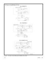
Page 124: ...124 TP 6694 9 20 Figure 54 20 150 kW Permanent Magnet Single Phase Alternators ADV 5875AB 1 ...
Page 125: ...TP 6694 9 20 125 Figure 55 20 300 kW Permanent Magnet Alternators ADV 5875AB 2 ...
Page 128: ...128 TP 6694 9 20 ...
Page 131: ...TP 6694 9 20 131 Figure 61 Battery Charger to Controller Connections DEC 3000 Controller ...
Page 153: ...TP 6694 9 20 153 Figure 90 Controller Wiring Connections GM78246G 1 ...
Page 154: ...154 TP 6694 9 20 Figure 91 Controller Wiring Connections GM78246G 2 ...
Page 171: ......


