Page 1: ......
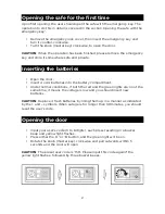
Page 2: ...dures of the new safe Schematic Drawing of Casing Schematic Drawing of Control Panel 1 Bolts 6 Green Light 2 Reset Button 7 Red Light 3 Battery Compartment 8 Yellow Light 4 Knob Master Key 9 Confirmation Button 5 Emergency Lock Cover 10 Power Supply 4 x AA Batteries Caution All drawings in this manual have been prepared based on the initial sample The exterior design or component positions of cons...
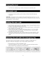
Page 3: ...e battery compartment Under normal conditions if both the red and the green lights are on at the same time it means the voltage is low and you should insert new batteries CAUTION Replace 4 fresh batteries by lining them up in a manner as indicated by the and symbols When outage is for longer than 30 minutes you should reset the user s code Opening the door Input your user s code 3 to 8 digits each...
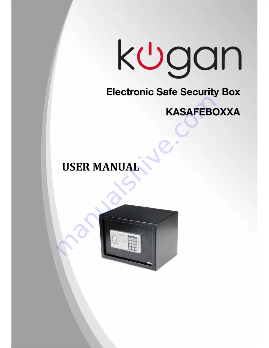
Page 4: ...e yellow light will go on At this point start inputting your desired code 3 Input your new code 3 8 digits then press either A or B to confirm There will then be 2 buzzer sounds indicating that the code has been accepted and stored in the memory 4 If the yellow light flashes with 3 buzzer beeps this means that the code changing has not been effective and you will need to try the sequence again Ope...