


Chapter 11 Appendix
MDC-7000/7900 Series
0093169010-10
11-32
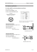
Alarm contact specification
Max. switching voltage 30 V
Max. current capacity 1 A
(Resistive load)
Note: Alarm contact will close in case of failure.
11.5.4 Serial data input/output specification (AIS)
Pin number
Signal name
1
Shield
2
IN-A
3
IN-B
4
OUT-B
5
OUT-A
6
GND
7
NC
8
NC
Data connector pin assignment
I/O connector AIS (J2)
Connector used: BD-08PMMP-LC7001
Connector acceptable: BD-08BFFA-LL6001
Serial data input (Listener):
Standard signals conforming to IEC61162-2 is
acceptable.
Input load
500 Ohm
Circuit configuration: Photo coupler
Type ACPL-M61 (Avago)
Serial data output circuit (Talker):
Standard signals conforming to IEC61162-2 can be
output.
Circuit configuration: RS422 Driver/Receiver IC
Type SN65HVD3085 (TI)
Serial data output circuit
Separated from ground level
1
2
3
4
7
8
5
6
J2
Data connector pin assignment
(Display unit upper view)
OUT-A
Data output
OUT-B
SN65HVD3085
Serial data output circuit
alarm
alarm
HY1Z-5V
For external device
IN-A
IN-B
500
Data input A
+Vcc
ACPL-M61
Data input B
Serial data input circuit
Summary of Contents for MDC-7010
Page 1: ......
Page 2: ......
Page 144: ... This page intentionally left blank ...
Page 170: ... This page intentionally left blank ...
Page 176: ... This page intentionally left blank ...
Page 192: ... This page intentionally left blank ...
Page 234: ......


