MDC-7000/7900 Series
Chapter 4 Setup after installation
0092669002-07
4-3
(5) Press ENT key to save the adjustment result.
Adjustable value: -180.0 to +180.0
Note: When you use inter-switch mode at first time, please set Heading (HL OFFSET) adjustment of
each antenna. These setting data are memorized in non-volatile memory, and applied
automatically when each antenna is selected.
4.1.3 Transmitting delay time adjustment (TX DELAY)
This adjustment is intended to match the picture on the radar display with the distance of an actual
target by the adjustment of the transmission delay time. For the most accurate adjustment, find a close,
hard, long, straight object such as a quay wall. Select or chose within 100 m an object for the best
result. Transmitting delay time is adjusted in accordance with the following procedures.
(1)
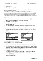
Change the range scale to 0.25 NM by pressing “+” (or “-”) key on the Operation unit.
(2)
Press MENU
key to display “Menu”.
Select [MAINTENANCE] => [STARTUP] => [TX DELAY] => [VALUE] will show the current
setting of the input value by highlighting the last digit value by the trackball.
(3)
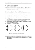
Move the TRACKBALL up or down to adjust the value to get a straight picture of the straight
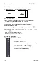
object in the display as shown in Figure 4.1.
(4)
Press ENT key to save the adjustment result.
Note: When you use inter-switch mode at first time, please set TX DELAY adjustment of each antenna.
These setting data are memorized in non-volatile memory, and applied automatically when each
antenna is selected.
Too near
Good
Too far
Figure 4.1 Picture display of Trigger Adjustment
Summary of Contents for MDC-7006
Page 1: ......
Page 2: ......
Page 44: ...Chapter 3 installation method MDC 7000 7900 Series 3 24 0092669002 07 Unit mm inch MRM 108 ...
Page 96: ... This page intentionally left blank ...
Page 134: ... This page intentionally left blank ...
Page 155: ...0092669002 07 A 1 INTER CONNECTION DIAGRAM RB807 ...
Page 156: ...A 2 0092669002 07 INTER CONNECTION DIAGRAM RB808 ...
Page 157: ...0092669002 07 A 3 INTER CONNECTION DIAGRAM RB809 ...
Page 158: ...A 4 0092669002 07 INTER CONNECTION DIAGRAM MRD 108 MRO 108 ...
Page 159: ...0092669002 07 A 5 INTER CONNECTION DIAGRAM MRM 108 MRO 108 ...
Page 160: ......

