Chapter 3 installation method
MDC-7000/7900 Series
3-38
0092669002-07
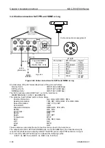
3.4.9 Cable connection for EPFS and SDME or Log
An initial value of the I/O format (Baud rate) of the port is as follows.
NAV port (J3):
IEC61162-2 (38400bps)
EPFS port (J5):
IEC61162-1 (4800 bps)
SDME port (J6):
IEC61162-1 (4800 bps)
The I/O format can switch IEC61162-1 or 2 in the radar menu.
[MAINTENANCE] => [I/O] => [BAUDRATE]
The sentence input to these ports is shown below.
Position information:
GLL, GGA, GNS, RMC, RMA
Heading information:
THS, HDT, HDG, HDM, VTG, RMC, RMA
Speed information:
VBW, VTG, VHW
Set and drift:
VDR
Waypoint information:
RMB, BWC, RTE, WPL
Routes:
RTE, WPL
Cross-track:
RMB, XTE
Datum:
DTM
Depth:
DBT, DPT
Temperature:
MTW
Date:
ZDA, RMC, GGA
LOP:
GLC
Wind:
MWD
ROT:
ROT
These sentences can select the port of each sentence input in the radar menu.
The output port is NAV, EPFS and SDME ports. As for the SDME port, the transmission cycle
is set at 0 seconds and not output by default. The EPFS port is output TTM sentence in a cycle
for 1 second by default.The NAV port is output at the following cycles.
EVE=1.0s, HBT=5.0s, OSD=1.0s, RSD=1.0s, TLB=5.0s
J7
SDME
(SPEED)
EPFS
(POSITION)
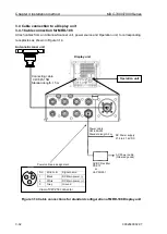
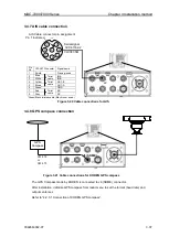
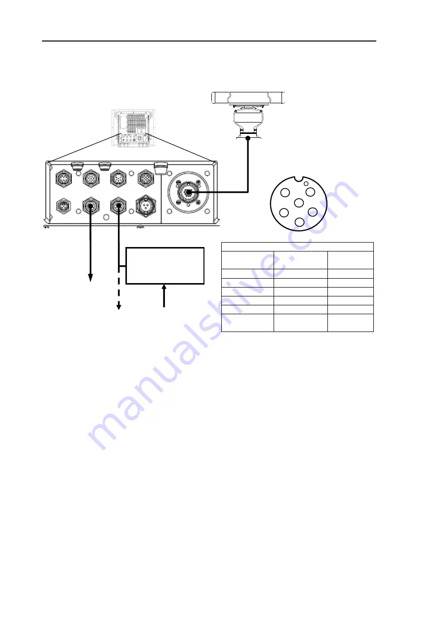
Figure 3.22 Cable connections for EPFS and SDME or Log
J5 & J6
Pin number
CW-376 wire
color
Signal
name
1
Blue+shield
Shield
2
White
OUT-A
3
Red
OUT-B
4
Orange
IN-A
5
Black
IN-B
6
Green
J5:12V
J6:NC
J5
J6
CW-376
CW-376
Log pulse NMEA
converter
(Option item: L1N)
Log pulse
1
2
3
4
5
6
Cable connector pin assignment
J5 (EPFS) J6 (SDME)
Summary of Contents for MDC-7006
Page 1: ......
Page 2: ......
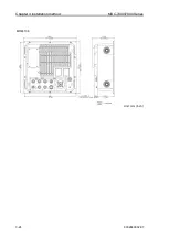
Page 44: ...Chapter 3 installation method MDC 7000 7900 Series 3 24 0092669002 07 Unit mm inch MRM 108 ...
Page 96: ... This page intentionally left blank ...
Page 134: ... This page intentionally left blank ...
Page 155: ...0092669002 07 A 1 INTER CONNECTION DIAGRAM RB807 ...
Page 156: ...A 2 0092669002 07 INTER CONNECTION DIAGRAM RB808 ...
Page 157: ...0092669002 07 A 3 INTER CONNECTION DIAGRAM RB809 ...
Page 158: ...A 4 0092669002 07 INTER CONNECTION DIAGRAM MRD 108 MRO 108 ...
Page 159: ...0092669002 07 A 5 INTER CONNECTION DIAGRAM MRM 108 MRO 108 ...
Page 160: ......

