MDC-7000/7900 Series
Chapter 3 Installation method
0092669002-07
3-35
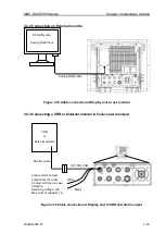
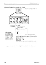
3.4.5 Connecting a Gyro converter unit or THD using Junction box JB-35
Note: It is necessary to set [JB-35 SET] menu to use JB-35. Refer to
“4.2.12 Setup JB-35”.
(Other)
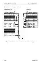
Figure 3.18 Cable connection of Display unit to Gyro converter unit or THD
Using Junction box JB-35
Please set the output of Gyro converter and THD
(gyro serial output) as follows.
Baud rate=38400bps
TX cycle=25ms-50ms
Sentence=THS or HDT
Checksum=ON
Please refer to the operation manual of each unit
for details.
Gyro synchro or Step signal
THD
OR
J3(NAV)
(Option)
Junction box
JB-35
Gyro converter
(Option: S2N)
Serial signal
IEC 61162-2
JB-35
Inter-switch data (NAV)
CW-376-5M
MASTER
SLAVE1
SLAVE2
SLAVE3
Pin
No.
CW-376
Wire color
Signal
name
1
Blue+shirld
GND
2
White
IN-A
3
Red
IN-B
4
Orange
OUT-A
5
Black
OUT-B
6
Green
+12V
Wiring of MASTER port of JB-35
Summary of Contents for MDC-7006
Page 1: ......
Page 2: ......
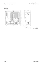
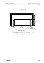
Page 44: ...Chapter 3 installation method MDC 7000 7900 Series 3 24 0092669002 07 Unit mm inch MRM 108 ...
Page 96: ... This page intentionally left blank ...
Page 134: ... This page intentionally left blank ...
Page 155: ...0092669002 07 A 1 INTER CONNECTION DIAGRAM RB807 ...
Page 156: ...A 2 0092669002 07 INTER CONNECTION DIAGRAM RB808 ...
Page 157: ...0092669002 07 A 3 INTER CONNECTION DIAGRAM RB809 ...
Page 158: ...A 4 0092669002 07 INTER CONNECTION DIAGRAM MRD 108 MRO 108 ...
Page 159: ...0092669002 07 A 5 INTER CONNECTION DIAGRAM MRM 108 MRO 108 ...
Page 160: ......

