Chapter 3 installation method
MDC-7000/7900 Series
3-32
0092669002-07
Operation unit
Power cable
CW-259-2M
Standard length: 2 m
AC Power cable,
(Ordered goods)
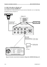
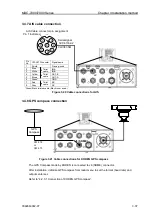
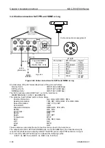
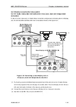
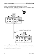
3.4 Cable connection to a Display unit
3.4.1 Cable connection for MRD-108
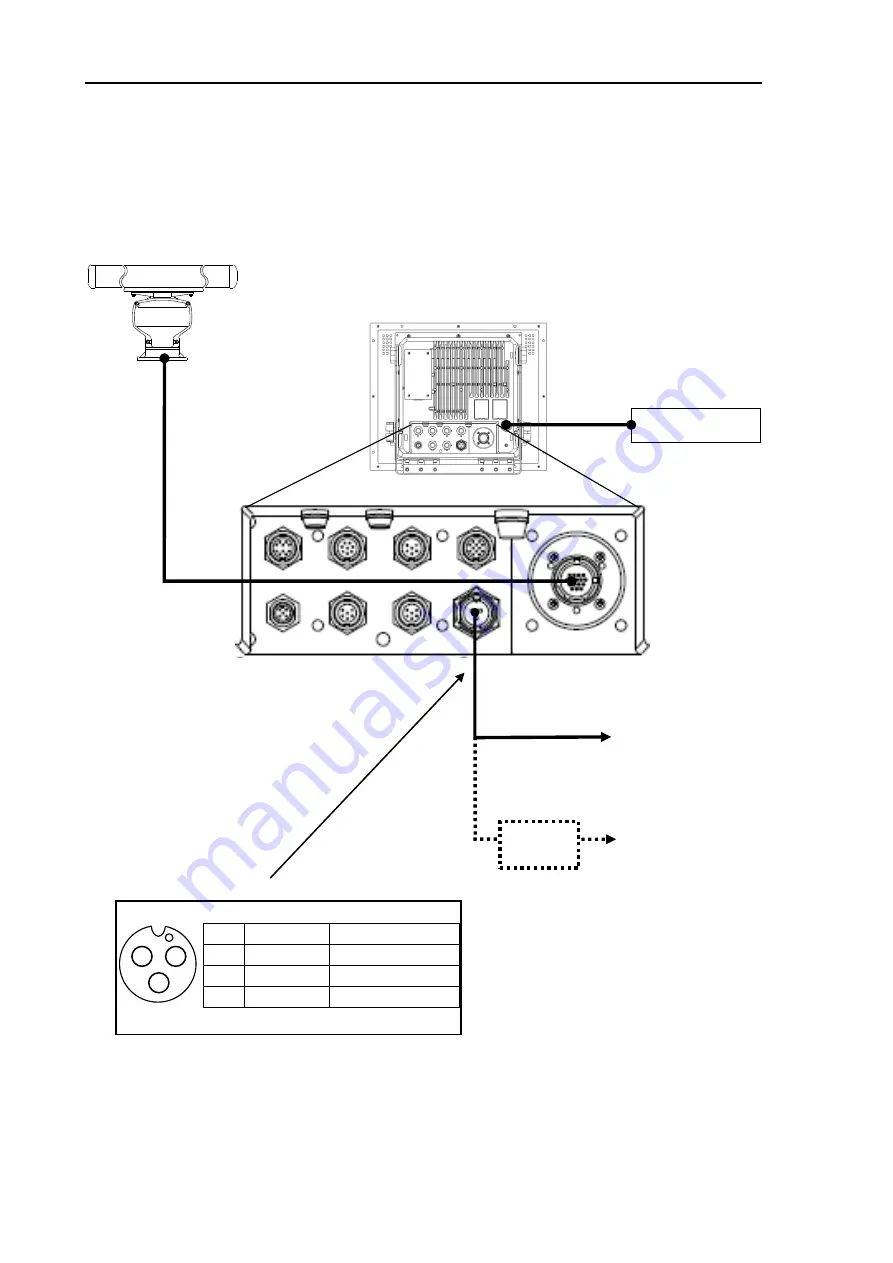
Attach cables from an Antenna-Scanner unit, power source and Operation unit, to corresponding
receptacles as shown in Figure 3.14.
View of CW-259 connector
Power cable pin assignment
No.
Wire color
Signal name
1
Black
DC Main power (-)
2
White
DC Main power (+)
3
Grey
Ground
1
2
3
Connecting cable
CW-845-15M
Standard length: 15 m
AC/DC Rectifier
PS-010
or
VL-PSG001
Figure 3.14 Cable connections for standard configuration of MRD-108 Display unit
Display unit
Antenna-Scanner unit
DC Power supply
21.6 to 41.6 VDC
Summary of Contents for MDC-7006
Page 1: ......
Page 2: ......
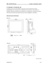
Page 44: ...Chapter 3 installation method MDC 7000 7900 Series 3 24 0092669002 07 Unit mm inch MRM 108 ...
Page 96: ... This page intentionally left blank ...
Page 134: ... This page intentionally left blank ...
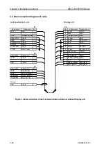
Page 155: ...0092669002 07 A 1 INTER CONNECTION DIAGRAM RB807 ...
Page 156: ...A 2 0092669002 07 INTER CONNECTION DIAGRAM RB808 ...
Page 157: ...0092669002 07 A 3 INTER CONNECTION DIAGRAM RB809 ...
Page 158: ...A 4 0092669002 07 INTER CONNECTION DIAGRAM MRD 108 MRO 108 ...
Page 159: ...0092669002 07 A 5 INTER CONNECTION DIAGRAM MRM 108 MRO 108 ...
Page 160: ......

