Chapter 5 Troubleshooting and on board repair
MDC-7000/7900 Series
5-10
0092669002-07
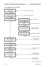
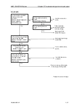
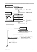
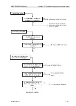
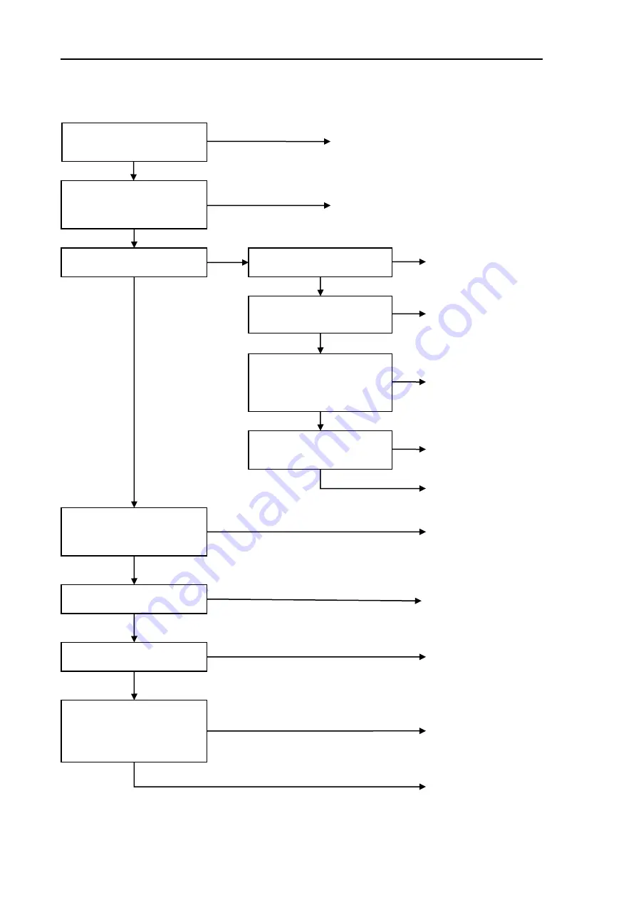
5.3.2.2 Cannot turn on the power
Is the power cable
connected?
Is the Operation unit cable
connected to the Display
unit correctly?
Is main fuse blown?
No
Yes
Correct the connection.
No
Correct the connection.
No
Yes
Remove antenna cable
connector from the display.
Is main fuse blown again?
Is power supply voltage
within normal range?
21.6 to 41.6 VDC
No
Reconnect to proper
power supply.
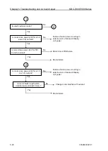
Does the voltage of
J710-17, 19, 21 pins on the
main logic PCB (E63-700*)
+12VDC ?
Yes
No
Power Supply PCB
(E63-600*) failure
Is fuse properly rated?
Yes
Exchange fuse.
Is inboard power polarity
correct?
Yes
No
Yes
Reconnect correctly
No
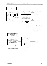
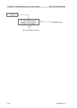
Is there not a contact point
in the antenna cable?
No
Power supply PCB
(E63-600*) failure
Yes
Antenna cable failure
No
Antenna unit failuer
Yes
No
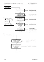
Connect connectors
correctly
Yes
Is power supple capacity
enough?
No
Change power supply
Do all connectors connect
properly?
Yes
Main logic PCB
(E63-700*) failure
Yes
*Subject to version change
Summary of Contents for MDC-7006
Page 1: ......
Page 2: ......
Page 44: ...Chapter 3 installation method MDC 7000 7900 Series 3 24 0092669002 07 Unit mm inch MRM 108 ...
Page 96: ... This page intentionally left blank ...
Page 134: ... This page intentionally left blank ...
Page 155: ...0092669002 07 A 1 INTER CONNECTION DIAGRAM RB807 ...
Page 156: ...A 2 0092669002 07 INTER CONNECTION DIAGRAM RB808 ...
Page 157: ...0092669002 07 A 3 INTER CONNECTION DIAGRAM RB809 ...
Page 158: ...A 4 0092669002 07 INTER CONNECTION DIAGRAM MRD 108 MRO 108 ...
Page 159: ...0092669002 07 A 5 INTER CONNECTION DIAGRAM MRM 108 MRO 108 ...
Page 160: ......

