MDC-2000 Series
Chapter 5 Installation
0093120005-02
5-1
Chapter 5
Equipment
5.1
Antenna Installation
Determining the location of the installation
The search capability of the radar varies largely, depending on the position of the antenna installation.
The ideal installation position is the high place over the keel line where no obstacle surrounds. Actually,
though there are many limitations in a ship, determine the installation position, considering the
following items.
1.
The antenna block should be over the line drawn between the bow and the stern, and should be
installed to a position where no obstacle to block the radiation path of the radar beam is present.
2.
To avoid the electromagnetic wave interference with human bodies, install the antenna block
higher than the living space by 0.6m. However, if installed at the higher position, objects at the
near distance cannot be searched. Thus, when approaching to a pier, if the radar is used, you
must pay attention.
The higher the position of the antenna is, the stronger the reflection from the sea surface
becomes.
3.
Keep the surface of the platform, where the antenna is installed, horizontal as possible to be
parallel with the sea surface.
4.
Install the antenna lock in front of the large structure and exhaust chimney to avoid the blind
sector (inability angle of image search) on the screen and to prevent the opening of the antenna
from being dirtied by the engine exhaust.
5.
Keep enough space for maintenance.
6.
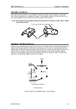
To prevent a blind or ghost from occurring in the heading, place the antenna towards the bow
rather than obstacles, keep it away from obstacles. And when installing the antenna on the mast,
place it in front of the mast. (If obstacles cannot be avoided due to limitation of structure, refer to
[How to shift the antenna from an obstacle] described later.
7.
Keep away the antenna from other equipment’s antenna.
Keep a distance from antennas of a direction finder and a VHF transmitter-receiver as far as
possible.
8.
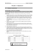
Keep a distance for safety from the magnetic compass.
Safety Distance from Magnetic Compass
Type of Scanner
Standard Compass
Steering Compass
RB715A 2.0m
1.4m
RB716A 2.0m
1.4m
RB717A 1.4m
0.95m
RB718A 1.4m
0.95m
WARNING
Install the antenna, keeping it away from wireless
equipment not to be interfered.
Summary of Contents for MDC-2000 series
Page 1: ......
Page 2: ......
Page 73: ...Chapter 6 Attached Table MDC 2000 Series 6 2 0093120005 02 ...
Page 74: ...MDC 2000 Series Chapter 6 Attached Table 0093120005 02 6 3 6 2 Specifications ...
Page 75: ...Chapter 6 Attached Table MDC 2000 Series 6 4 0093120005 02 6 3 External View Unit mm inch ...
Page 82: ......

