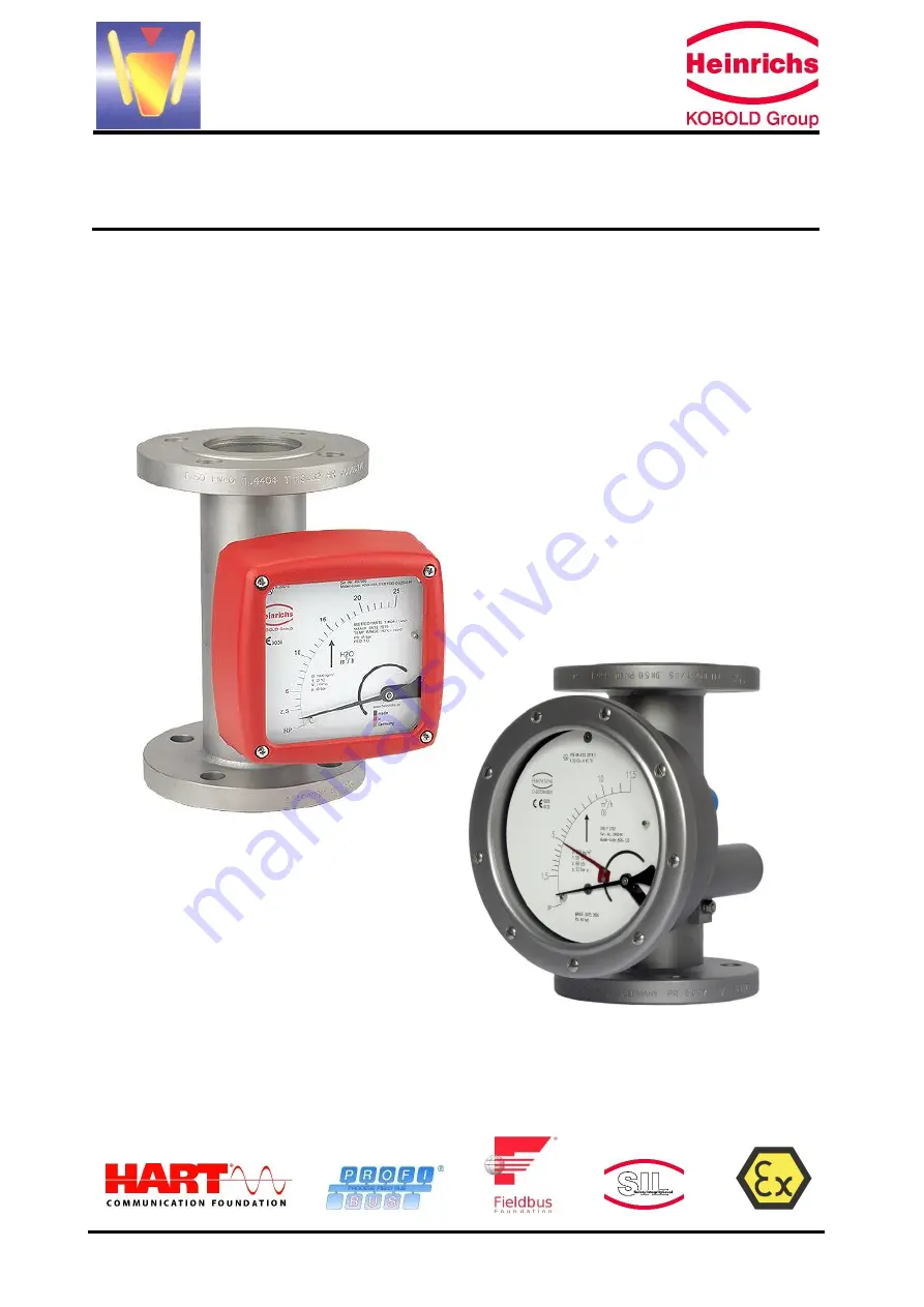
Variable-Area Flow Meter
BGN
Installation and Operating Instructions
Page 1: ...Variable Area Flow Meter BGN Installation and Operating Instructions...
Page 2: ...erature 7 9 2 Influence of fluid temperature 7 10 CONDITIONS OF USE 7 10 1 Mounting requirements 8 10 1 1 Mounting start up 8 10 1 2 Device settings 9 10 1 3 Adjusting the switch point for the inducti...
Page 3: ...S CERTIFICATES AND APPROVALS 22 17 MAINTENANCE 22 18 INSTALLING AND REMOVING CONE FLOAT DAMPING SETS SPRING STOP 22 19 TROUBLE SHOOTING 23 20 RETURNING DEVICES FOR REPAIR AND SERVICE 23 22 EXPLODED VI...
Page 4: ...ns The BGN meter is suitable for flow measurement of liquid or gaseous products in pipes It shows the current flow rate in volume or mass per unit in time Please consider also the provisions for the u...
Page 5: ...the top through the measuring ring lifting the float until the buoyancy force A and the weight of the float establish equilibrium As the height of the float varies an annular clearance proportional to...
Page 6: ...y class PTB Nr 99 ATEX 2219 X PTB Nr 00 ATEX 2048 X BGN flow meters can be equipped with max 2 switches Measuring range chart BGN DN 1 8 EN1092 1 ASME 8 B16 5 2003 Flow Body S st st P PTFE H Hastelloy...
Page 7: ...proval documents must be followed See section 10 1 5 8 3 Model ES PPA and ES FF The ES PPA and ES FF transmitters are FISCO field devices that are connected via a two wire field bus circuit according...
Page 8: ...e device must be mounted in accordance with the direction of flow from the bottom to the top perpendicularly Please observe the prior reference to the BGF type device The nominal size of the device an...
Page 9: ...ccording to your order specifications The limit switches are set to the desired values If you have submitted no requirements the basic settings are 1 switch Minimum contact switching point at 10 of de...
Page 10: ...rking may also be operated in hazardous areas Ambient Temp Process Temp Marking Z o n e Description Max Ambient temperature 40 C 80 C 25 C 150 C II 2G Ex h IIC T6 T3 Gb II 2D Ex h IIIC T85 C T200 C Db...
Page 11: ...or must be operated in the T5 temperature class with an intrinsically safe circuit that does not exceed the maximum values of the Type 3 circuit When using the device in hazardous areas follow the app...
Page 12: ...for equipotential bonding 10 2 Ambient conditions 10 2 1 Ambient temperature ranges Without electrical accessories 40 C to 80 C With limit switches 40 C to 80 C Observe the type certificate of the co...
Page 13: ...100 110 120 130 140 150 160 170 180 190 200 max Umgebungstemperatur C Messstofftemperatur C Standardausf hrung DN15 25 DN40 50 DN80 100 55 56 57 58 59 60 61 62 63 64 65 66 67 68 69 70 70 80 90 100 110...
Page 14: ...sity Liquids up to 2 0 kg l Gases no restrictions 10 2 13 Viscosity The influence of viscosity depends on various factors Therefore it must be calculated for each application 10 2 14 Pressure for gas...
Page 15: ...in acc with DIN EN DN 15 1 2 or DN 251 1 PN 40 Flange in acc with ASME 150 lbs 1 DN 25 flange is a special version Pipe NPT f G f in PN CL SW A mm S15 1 4 3 8 1 2 3 4 40 300 36 77 0 S25 1 4 3 8 1 2 3...
Page 16: ...on with threaded connection 100 mm for displaced indicator Pipe Size DN ANSI PN CL l W mm A mm S15 15 1 2 40 300 26 99 5 S25 25 1 40 300 32 102 6 S40 40 11 2 40 300 46 110 4 S50 50 2 40 300 70 123 4 S...
Page 17: ...00 lbs ASME B16 5 4 9 5 6 S40 1 300 lbs ASME B16 5 7 4 8 1 S50 2 300 lbs ASME B16 5 8 9 9 6 S80 3 300 lbs ASME B16 5 16 2 16 9 S1H 4 300 lbs ASME B16 5 24 6 25 3 SH5 6 300 lbs ASME B16 5 49 7 50 2 Fit...
Page 18: ...nections food connection e g TriClamp welding connection The S H versions in special design are available for higher pressure on request 11 5 Magnetic filter The BGN flow meter is sensitive to impure...
Page 19: ...guarantee Cable glands are not part of the delivery The cable gland must the specified outer dimeter The cable gland must fit to the diameter of the cable The cable must form a pig tale in front of t...
Page 20: ...perating Instructions Page 20 of 34 Subject to change without notice 11 6 2 Wiring diagram for ES transmitter with 4 20 mA output and 2 limit switches 11 6 3 Wiring diagram for ES transmitter with 4 2...
Page 21: ...e standard cable length is 2 5 m The cable has 7 wires yellow green for earth and 6 black wires with white numbers 1 6 The function of the wires 1 6 corresponds to the terminal numbers If the connecti...
Page 22: ...the measuring pipe with hammering from outside see Removing installing the cone float The switch points of the limit switches are adjustable To do this remove the indicator cover unfasten the contact...
Page 23: ...Un known Sent the instrument back to the manufacturer and include a detailed failure description 20 Returning devices for repair and service Note In accordance with the applicable German waste disposa...
Page 24: ...ting with measuring element 22 1 1 BGN Standard version 22 1 2 BGN with spring stop 22 1 3 BGN with damping piston 22 1 4 BGN with damping piston and spring stop Name Figures 12 15 Part no BGN Fitting...
Page 25: ...w o ring 40 Cable gland blue intrinsically safe c w o ring M20 x 1 5 41 Cable gland grey ATEX c w o ring M20 x 1 5 42 Scale blank 50 Fixing screw for the scale 60 Zero point screw with nut 70 Indicato...
Page 26: ...icator unit with local scale 22 2 2 Complete indicator unit c w 1 pc limit switch SJ 3 5 N 22 2 3 Complete Indicator unit with 2 pcs limit switches SJ 3 5 N 22 2 4 Complete indicator unit with 1 pc SP...
Page 27: ...ik BGN Installation and Operating Instructions Page 27 of 34 Subject to change without notice 22 2 5 Complete indicator unit with 2 pcs SPDT micro switches KEM 22 2 6 Complete Indicator unit with tran...
Page 28: ...B2220 221R Class 300 RF ASME B16 5 2003 reduced raised face diameter 407F 15A 16K FF JIS B2220 202R Class 150 RF ASME B16 5 2003 222R Class 300 RF ASME B16 5 2003 Thread connections installation lengt...
Page 29: ...removable 4070 G2 female thread 6080 2 NPT f 350mm 4080 G2 1 2 female thread 6090 2 1 2 NPT f 350mm 4090 G3 female thread 6092 3 NPT f 350mm 1H Flange connections 335B DN100 PN16 Form B1 DIN EN 1092 1...
Page 30: ...sure compensation Process temperature 150 C for electrical output Process temperature 200 C for local indication W Standard display housing with pressure compensation forward advanced process temperat...
Page 31: ...rmful caustic radioactive explosive oxidizing biological harmful other we have carried out the following things all cavities have been tested to be free the used process media all cavities are rinsed...
Page 32: ...eit EU Directive relating to electromagnetic compatibility 2014 34 EU ATEX EU Richtlinie ber Ger te zur Bestimmungsgem e Verwendung in explosionsgef hrdeten Bereichen EU Directive relating to electric...
Page 33: ...Anschrift der Notifizierte Stelle Name and Address of the Notified Body T V S D Industrie Service GmbH T V S D Gruppe Westendstra e 199 D 80686 M nchen ID Nr ID No L 2014 68 EU 0036 DEKRA EXAM GmbH C...
Page 34: ...he Declarations of Conformity are provided by the switch manufacturer on their homepage Die oben genannten Produkte entsprechen der Richtlinie 2014 34 EU Neue Editionen k nnen bereits eine oder mehrer...