Kleenmaid KED2000 Repair Instructions Download Page 17


6 FAULT 

DIAGNOSTICS 

2. S

c

Obs

c


Display 

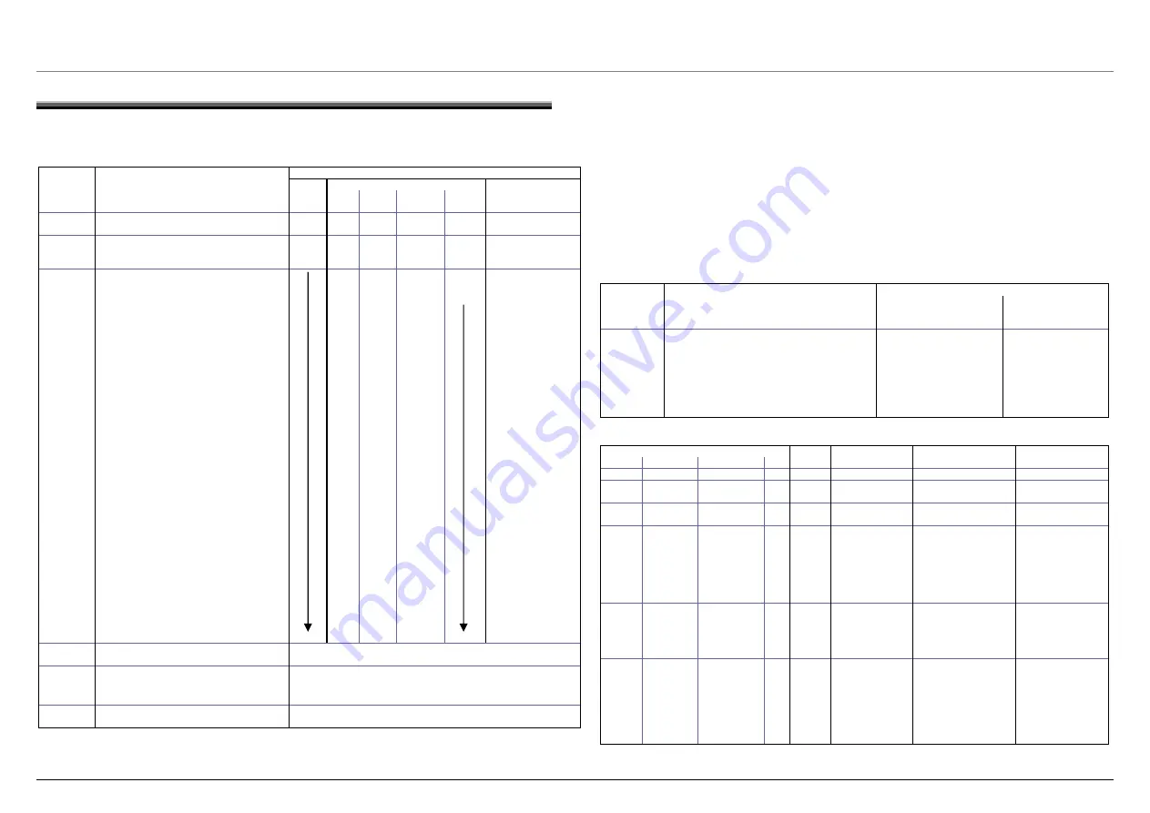
ele ting the test program


erve  orrect method for setting program selector! 

LEDs(Indicator) 


y Cupboard 

dry 

End 

Display 


Button 
LED Drying Iron 

dr

Activ

e

men


ate t st  Program selector switch to OFF position 

Off  

u: 


One time last error 

Turn the appliance on by pressing the Start 
and Delicates button simultaneously and 

Start is 
flashing 


turning the selector switch (either direction).  quick 

Activ

e

is 
flashing 
quick 


ate t st  In test menu set program selector switch to    


program: 

a test program:  


Read out error storage 


1st position to the right 


2nd position to the right 

Test program for safety test 


3rd position to the right 

Display test (LED/LCD) 


4th position to the right 

Control elements test 


5th position to the right 

Consumer test 


6th position to the right 

Laundry resistance measurement test 


7th position to the right 

Demo program 


8th position to the right 

Changeover 10A/16A (208V/240V) 

operation 


1st position to the left 

Automatic end-of-line program 


Start test 
program: 

Press START button 

LED Start is illuminating 

Abort test 
program: 

Adjust program selector switch or press 
START button 

LED Start is flashing 


Switch off appliance  


Leave test 
program: 

Switch off appliance 


t on one side with the phase ) switch on. The test must be done using 

For this propose the following Inspection Process is adaptive 

Connect app

ine 

tton Extra dry 

4. 

The current consumption on tester  (Motor and Heater Elements must be switch on) 

1. Safety test 

For the safety test must Heater Element (at leas
different current method. 

1. 

liance with tester and power l

2. 

Choose program with Heater; example Co

3. Program 

start 

The Maximal Different Current must be under allowable limit while checking procedures is running.


Annotation: 

Depending on used tester (for example Meratester 5-f) can be necessary inspection process with 180° twisted power 
connector ones again do. 
Inspection Process must be done with cold Appliance to prevent that Heater Element is switch on. 


2.1 Fault display


Display 

Test: Sequence: 

Standard Indicator 

Display 
E: failure number 
C: numbers of failure 

Last fault 

- the last fault is displayed at first 

Start and finished LED’s are  E:XX is displayed 
flashing 

Fault history  - after further operation the START button, the 

content of the error register (of the last 8 cycles) 
is indicated 

LED Start is illuminating 
Status-LED’s: failure code 

E:XX is displayed 
C:XX is displayed 
Or blank if no failure 

Last fault 

- if all register were indicated, the first fault is 

Filter- outflow hose  LEDs 

E:XX is displayed 

displayed again by operation the START button  are flashing 

C:XX is displayed 
Or blank if no failure 


LEDs (Indicator) 

Drying 

Iron dry 

Cupboard dry  End 

description 

cause 

Display 

Fault / fault 

Remarks, possible 

Results 


 No 

fault   


is 
flashing 


E:11 

Fluffing level 1 

- Fluff filter, container 
or air routes blocked 

- Clean components 
and air routes 


is flashing   


E:12 

Fluffing level 2 

- Fluff filter, container 
or air routes blocked 

- Clean components 
and air routes 

is 
flashing 

is flashing   


E:13 

Maximum drying 
time exceeded 

- Heater or heater 
control damaged 
- Bimetal switch was 
triggered 
- Laundry  load (to 
heavy or to wet) 

- Check heating 
circuit and bimetal 
switch, replace 
damaged parts 
- Reduce laundry 
load or select 
adequate program 

is
fl


ashing 


is flashing 


E:15 

Fault in heating 
circuit 

- Excess temperature
 of the heater is 
detected 

- Check air routes, 
heater function and 
heater control; 
replace damaged 
parts 

is
fl


ashing 

is flashing  is flashing 


E:17 

Door-NTC fault 
(TD) 

- Damaged sensor 
- Short circuit in sensor 
wire 
- Open sensor circuit 
- Control interpretation 
fault 

- Check wires and 
connectors, replace 
damaged parts 
- Short circuits and 
breaks are detected 
by control after 
switch-on 


702_58300000121945_ara_en_a 

Page 17 of 21 

Summary of Contents for KED2000

Page 1: ...t vents 3 2 3 Feet leveling legs 3 3 OPERATION 4 3 1 Controls 4 4 COMPONENTS 5 4 1 Dryer Components 5 5 REPAIR 9 5 1 Disassembly Reassembly 9 5 2 Diagnosing troubleshooting 13 5 3 Dryer noise 14 5 4 C...

Page 2: ...ning service c Carefully follow all servicing instructions Verify the instructions if there are any that you don t fully understand c Read and heed all Cautions and Warnings on the appliance and those...

Page 3: ...p connector notch with the vent tab 2 2 2 Installing vent ducts For best drying use shortest possible duct length and fewest of elbows Use the table below when selecting ducting 90 Turns Maximum Lengt...

Page 4: ...er LED Reminder only to clean the lint filter There is no sensor showing lint levels LED indicator lights Program cycle selector knob Additional options buttons Menu chooses options and Select changes...

Page 5: ...and a manually resettable hi limit temperature protector NTC temperature sensor Heater terminals Front bearing shield Control module Push red button to reset Hi limit protector Hi limit protector Fan...

Page 6: ...ally reset by pushing the left plunger in viewing rear of dryer the dryer will not run if the switch hasn t been reset 4 1 5 Air exhaust duct Air exhaust duct connects to the fan and allows exhausting...

Page 7: ...oor pin Door pin engages the door switch notifying the dryer the door is closed for drying If the door pin is damaged the entire door assembly must be replaced A T 20 screw on the door pin cover can b...

Page 8: ...lacing the seal make sure all old adhesive is removed and no new adhesive gets onto the drum Any excess adhesive or residue may cause squeaking 4 1 12 Drum with bands Drums have two steel bands around...

Page 9: ...d knob Don t cut cable mounts cut cable ties holding cables to mounts When reassembling use new cable ties 5 1 3 Top panel worktop Remove two T 20 Torx screws with washers from rear of dryer slide pan...

Page 10: ...once drum cover has been removed 4 Drum sleeve bearing can be removed from drum cover by removing four T 20 Torx screws Drum sleeve bearing Outer bearing race Drum axle 5 1 6 Heater Drum Drum cover Be...

Page 11: ...cradle 5 1 8 Front panel and bearing shield 1 Remove fascia panel 5 1 1 If necessary for access remove top panel 5 1 3 2 Remove door and door hinge 3 Remove two T 20 Torx screws at top and bottom of...

Page 12: ...g fan hold motor shaft not motor rotor fins to avoid damaging fins 5 1 10 Anti Crease end light If the Anti Crease end light is on while the display is off an internal switch S3 on the control board h...

Page 13: ...utout tripped Clean lint screen and clean lint and other debris from front shield then replace hi limit Also check exhaust duct length of elbows Heating element failed Check voltages to and resistance...

Page 14: ...f fresh air and then turn dryer off and on again No program selected Select program Light bulb defective light bulb burned out Change light bulb No power supply Guarantee power supply Drum light doesn...

Page 15: ...Turn dryer off and on again Unsuitable program selected gram and then Select suitable pro turn dryer off and on again Maximum drying time exceeded Clean filter and exhaust air duct Spin laundry at a...

Page 16: ...diately stop dryer by rota Off position then open do 2 Remove and clean filter 3 Replace filter and let dryer cool down 4 Close door then rotate cycle selector knob to desired cycle and press If the w...

Page 17: ...tester for example Meratester 5 f can be necessary inspection process with 180 twisted power connector ones again do Inspection Process must be done with cold Appliance to prevent that Heater Element...

Page 18: ...or LCD segments are illuminating n All LEDs and s CD segments are activated All LEDs and or LCD segments are illuminating successive in 0 5 sec steps All LEDs and or L successive in 0 5 sec steps Sequ...

Page 19: ...n Off blank 10 1 s On blank Off 11 1 s On Off blank 12 1 s On blank Off 13 1 s On Off blank 14 1 s Off On blank 15 10 s only drying LED ON Counts from 0 30 to 0 20 descending Off 16 10 s Off only Damp...

Page 20: ...if so ontrol is OK and shouldn t be replaced If heater and motor turn on together during Step 2 relay has failed and control must be changed ay is on ule relay diagnostics on the control If heat g e...

Page 21: ...lbows Rigid Duct Flexible Duct 0 20 m 14 m 1 17 m 11 m 2 14 5 m 9 m 3 12 m 7 m 4 9 m 5 m 7 1 7 Air flow volume flow rate vs exhaust duct length 100 110 120 130 140 150 160 170 180 190 200 210 220 230...

Reviews: