background image

INSTALLATION INSTRUCTIONS  

SLIDE-IN DUAL-FUEL RANGES

INSTRUCTIONS D’INSTALLATION DES CUISINIÈRES 

AUX BI-COMBUSTIBLES ENCASTRABLES

IMPORTANT:

Save for local electrical inspector's use.

IMPORTANT :

À conserver pour consultation par l'inspecteur local des installations électriques.

W11124008A

Table of Contents/Table des matières

RANGE SAFETY .............................................................................2
INSTALLATION REQUIREMENTS .................................................4

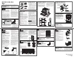
Tools and Parts .............................................................................4
Location Requirements ................................................................4
Electrical Requirements - U.S.A. Only .........................................7
Electrical Requirements - Canada Only .......................................8
Gas Supply Requirements ...........................................................8

INSTALLATION INSTRUCTIONS .................................................10

Unpack Range............................................................................10
Install Anti-Tip Bracket ...............................................................10
Adjust Leveling Legs ..................................................................11
Level Range ................................................................................12
Electrical Connection - U.S.A. Only ...........................................12
Make Gas Connection ...............................................................18
Verify Anti-Tip Bracket Is Installed and Engaged ......................19
Electronic Ignition System .........................................................20
Remove/Replace Drawer ...........................................................20
Oven Door ..................................................................................21
Complete Installation .................................................................21

GAS CONVERSIONS ....................................................................22

Propane Gas Conversion ...........................................................22
Natural Gas Conversion .............................................................24
Adjust Flame Height ...................................................................26

SÉCURITÉ DE LA CUISINIÈRE ...................................................27
EXIGENCES D’INSTALLATION ...................................................29

Outils et pièces ...........................................................................29
Exigences d’emplacement .........................................................29
Spécifications électriques – Canada seulement .......................32
Spécifications de l’alimentation en gaz .....................................32

INSTRUCTIONS D’INSTALLATION .............................................34

Déballage de la cuisinière ..........................................................34
Installation de la bride antibasculement ....................................34
Réglage des pieds de nivellement .............................................35
Réglage de l’aplomb de la cuisinière .........................................36
Raccordement au gaz ................................................................36
Vérifier que la bride antibasculement est bien installée  

et engagée ..................................................................................38
Système d’allumage électronique..............................................39
Dépose et réinstallation du tiroir ................................................39
Porte du four ..............................................................................40
Achever l’installation ..................................................................41

CONVERSIONS POUR CHANGEMENT DE GAZ ......................42

Conversion pour l’alimentation au propane ..............................42
Conversion pour l’alimentation au gaz naturel ..........................44
Réglage de la taille des flammes ...............................................47

Summary of Contents for KSDB900ESS2

Page 1: ...ctronic Ignition System 20 Remove Replace Drawer 20 Oven Door 21 Complete Installation 21 GAS CONVERSIONS 22 Propane Gas Conversion 22 Natural Gas Conversion 24 Adjust Flame Height 26 SÉCURITÉ DE LA CUISINIÈRE 27 EXIGENCES D INSTALLATION 29 Outils et pièces 29 Exigences d emplacement 29 Spécifications électriques Canada seulement 32 Spécifications de l alimentation en gaz 32 INSTRUCTIONS D INSTALL...

Page 2: ...proved by UL or CSA For more information contact your gas supplier If a gas leak is detected follow the What to do if you smell gas instructions WARNING If the information in these instructions is not followed exactly a fire or explosion may result causing property damage personal injury or death Do not store or use gasoline or other flammable vapors and liquids in the vicinity of this or any othe...

Page 3: ...lled Install anti tip bracket to floor or wall per installation instructions Slide range back so rear range foot is engaged in the slot of the anti tip bracket Re engage anti tip bracket if range is moved Do not operate range without anti tip bracket installed and engaged Failure to follow these instructions can result in death or serious burns to children and adults Anti Tip Bracket To verify the...

Page 4: ...oven door on the top right hand side of the oven frame The range should be located for convenient use in the kitchen Recessed installations must provide complete enclosure of the sides and rear of the range All openings in the wall or floor where range is to be installed must be sealed Cabinet opening dimensions that are shown must be used Given dimensions are minimum clearances Parts Needed If us...

Page 5: ...ufactured Home Installations ANSI A225 1 NFPA 501A or with local codes In Canada the installation of this range must conform with the current standards CAN CSA A240 latest edition or with local codes Mobile Home Installations Require When this range is installed in a mobile home it must be secured to the floor during transit Any method of securing the range is adequate as long as it conforms to th...

Page 6: ...nstallation of rigid gas pipe and grounded outlet H 13 33 3 cm I 7 19 5 cm J 4 12 2 cm K 3 9 4 cm plus measurement of M L Cabinet door or hinges should not extend into the cutout M Remaining counter depth shou ld not exceed 2 5 7 cm L A B C D E F M H I J K G J A 18 45 7 cm upper side cabinet to countertop B 13 33 cm max upper cabinet depth C 30 76 2 cm min opening width D For minimum clearance to ...

Page 7: ...um cable See the Electrical Connection U S A Only section Allow at least 6 ft 1 8 m of slack in the line so that the range can be moved if servicing is ever necessary A UL listed conduit connector must be provided at each end of the power supply cable at the range and at the junction box Wire sizes and connections must conform with the rating of the range The tech sheet and wiring diagram are loca...

Page 8: ...atest edition or CAN CGA B149 latest edition IMPORTANT Leak testing of the range must be conducted according to the manufacturer s instructions Type of Gas Natural Gas This range is factory set for use with Natural gas See Gas Conversions section The model serial rating plate located on the oven frame behind the top right hand side of the oven door has information on the types of gas that can be u...

Page 9: ...14 35 5 cm WCP Propane Gas Minimum pressure 11 28 cm WCP Maximum pressure 14 35 5 cm WCP Contact local gas supplier if you are not sure about the inlet pressure Burner Input Requirements Input ratings shown on the model serial rating plate are for elevations up to 2 000 ft 609 6 m For elevations above 2 000 ft 609 6 m ratings are reduced at a rate of 4 for each 1 000 ft 304 8 m above sea level not...

Page 10: ...re people to move and install range Failure to do so can result in back or other injury Install Anti Tip Bracket 1 Remove the anti tip bracket from the inside of the oven 2 Determine which mounting method to use floor or wall If you have a stone or masonry floor you can use the wall mounting method If you are installing the range in a mobile home you must secure the range to the floor This anti ti...

Page 11: ...tion NOTE To place range back up into a standing position put a sheet of cardboard or hardboard in front of range Using 2 or more people stand range back up onto the cardboard or hardboard 2 Measure the distance from the top of the counter to the floor 3 Measure the distance from the top of the cooktop to the bottom of the leveling legs This distance should be the same If it is not adjust the leve...

Page 12: ...liers to adjust leveling legs up or down until the range is level NOTE Range must be level for satisfactory baking performance and best cleaning results using AquaLift Self Clean Technology Electrical Connection U S A Only If your home has a 3 or 4 wire receptacle continue with Install Using a Power Supply Cord If your home has a 3 or 4 wire direct connection go to Install Using Direct Wire Instal...

Page 13: ...k wires to the outer terminal block posts with 10 32 hex nuts 4 Firmly tighten hex nuts NOTE For power supply cord replacement use only a power cord rated at 250 volts minimum 40 or 50 amps that is marked for use with nominal 1 8 3 5 cm diameter connection opening with ring terminals and marked for use with ranges 5 Tighten strain relief screws IMPORTANT Verify the tightness of the hex nuts 6 Repl...

Page 14: ...k section The ground wire must be attached over the ground link section 5 Use 8 1 0 cm nut driver to connect the neutral white wire to the center terminal block post with one of the 10 32 hex nuts 6 Connect line 2 red and line 1 black wires to the outer terminal block posts with 10 32 hex nuts 7 Firmly tighten hex nuts NOTE For power supply cord replacement use only a power cord rated at 250 volts...

Page 15: ...Strip the insulation back 8 1 0 cm from the end of each wire 2 Allow enough slack in the wire to easily attach the wiring terminal block 3 Complete installation following instructions for your type of electrical connection 4 wire recommended 3 wire if 4 wire is not available Electrical Connection Options WARNING Electrical Shock Hazard Disconnect power before servicing Use 8 gauge copper or 6 gaug...

Page 16: ...al lugs to the terminal block 20 lbs in 2 3 N m 3 Use 8 1 0 cm nut driver to connect the bare green ground wire to the center terminal block post with one of the 10 32 hex nuts 4 Connect line 2 red and line 1 black wires to the outer terminal block posts with 10 32 hex nuts 5 Firmly tighten hex nuts IMPORTANT Verify the tightness of the hex nuts 6 Replace lower access cover A Terminal block B Grou...

Page 17: ...bs in 2 3 N m 5 Use a hex or Phillips screwdriver to connect the bare green ground wire to the range with the ground link screw and ground link section The ground wire must be attached over the ground link section and must not contact any other terminal 6 Use 8 1 0 cm nut driver to connect the neutral white wire to the center terminal block post with one of the 10 32 hex nuts 7 Connect line 2 red ...

Page 18: ...h adapters being certain not to move or turn the gas pressure regulator 3 Use a 15 16 2 4 cm combination wrench and an adjustable wrench to attach the flexible connector to the adapters IMPORTANT All connections must be wrench tightened Do not make connections to the gas regulator too tight Making the connections too tight may crack the regulator and cause a gas leak Do not allow the regulator to ...

Page 19: ...sually check that the rear range foot is inserted into the slot of the anti tip bracket On Ranges Equipped with a Warming Drawer or Baking Drawer 1 Slide range into final location making sure rear leveling leg slides into anti tip bracket Leave a 1 2 5 cm gap between the back of the range and the back wall 2 Place the outside of your foot against the bottom front of the warming drawer or baking dr...

Page 20: ...e gas line If Burners Do Not Light Properly Turn cooktop control knob to the off position Check that the range is plugged into a grounded 3 prong outlet Check that the circuit breaker has not tripped or the household fuse has not blown Check that the gas shutoff valves are set to the open position Check that burner caps are properly positioned on burner bases Repeat start up If a burner does not l...

Page 21: ...se of recycle all packaging materials 5 Check that the range is level See the Level Range section 6 Use a mild solution of liquid household cleaner and warm water to remove waxy residue caused by shipping material Dry thoroughly with a soft cloth For more information see the Range Care section of the User Guide 7 Read the User Guide 8 Turn on surface burners and oven See the User Guide for specifi...

Page 22: ...instructions Slide range back so rear range foot is engaged in the slot of the anti tip bracket Re engage anti tip bracket if range is moved Do not operate range without anti tip bracket installed and engaged Failure to follow these instructions can result in death or serious burns to children and adults A B C A To range B Shutoff valve closed position C Gas supply line A A Gas pressure regulator ...

Page 23: ...nt Fully insert choke into bottom of x large burner base Choke should snap into place NOTE Use only for spreader bases marked XL Propane Gas Orifice Spud Chart for Surface Burners Not in all kits models NOTE Refer to the model serial rating plate located on the oven frame behind the top right hand side of the oven door for proper sizing of spuds for each burner location 6 Place Natural gas orifice...

Page 24: ...screw the metal cover and unscrew the blue regulator cap Keep the washer in place 4 Flip the blue regulator cap over and screw it back into the metal cover 5 Screw the metal cover securely back into place Do not overtighten A A Gas pressure regulator Natural Gas Conversion A Metal cover B Washer C Blue regulator cap A B A C A LP gas position B Natural gas position A B Complete Installation Natural...

Page 25: ...tural Gas Orifice Spud Chart NOTE Refer to the model serial rating plate located on the oven frame behind the top right hand side of the oven door for proper sizing of spuds for each burner location 6 Place Propane gas orifice spuds in the orifice spud bag IMPORTANT Keep the Propane gas orifice spuds in case of reinstallation with Propane gas 7 Replace the burner base 8 Replace burner cap 9 Repeat...

Page 26: ...l decrease the flame size 3 Replace the control knob 4 Test the flame by turning the control from the low position to the high position checking the flame at each setting 5 Repeat the previous steps for each burner A Low flame B High flame A B A B C A Control knob stem B Screwdriver C Pliers To Adjust Double Burner On Some Models 1 Light burner and turn to lowest setting where both inner and outer...

Page 27: ... information contacter le fournisseur de gaz local En cas de détection d une fuite de gaz exécuter les instructions Que faire dans le cas d une odeur de gaz AVERTISSEMENT Si les renseignements dans ces instructions ne sont pas exactement observés un incendie ou une explosion peut survenir causant des dommages au produit des blessures ou un décès Ne pas entreposer ni utiliser de l essence ou d autr...

Page 28: ...u mur conformément aux instructions d installation Faire glisser de nouveau la cuisinière de façon à ce que le pied arrière de la cuisinière se trouve dans la fente de la bride antibasculement Réengager la bride antibasculement si la cuisinière a été déplacée Ne pas faire fonctionner la cuisinière si la bride antibasculement n est pas installée et engagée Le non respect de ces instructions peut ca...

Page 29: ...c cosses rondes ou en fourche à pointes relevées à l extrémité de chaque conducteur Un serre câble homologation UL Consulter les codes locaux en vigueur et le fournisseur de gaz Déterminer les caractéristiques des sources disponibles d électricité et gaz Voir la section Spécifications électriques et Spécifications de l alimentation en gaz correspondante Il est recommandé de faire réaliser tous les...

Page 30: ...nstallation doit satisfaire aux critères de la norme Standard for Manufactured Home Installations ANSI A225 1 NFPA 501A ou aux dispositions des codes locaux Au Canada l installation de cette cuisinière doit satisfaire aux stipulations de la version la plus récente de la norme CAN CSA A240 ou des codes locaux en vigueur Autres critères à respecter pour une installation en résidence mobile Dans le c...

Page 31: ...alisation de gaz rigide et de la prise reliée à la terre dans cette zone grisée H 13 33 3 cm I 7 19 5 cm J 4 12 2 cm K 3 9 4 cm plus la mesure de M L La porte du placard ou ses ch arnières ne doit pas dépasser à l intérieur de l ouverture M La profondeur restante du plan de travail ne doit pas dépasser 2 5 7 cm L A B C D E F M H I J K G J A 18 45 7 cm entre le placard latéral supérieur et le plan ...

Page 32: ...cal l installation doit satisfaire aux prescriptions de la plus récente édition du National Fuel Gas Code ANSI Z223 1 American National Standard ou CAN CGA B149 édition la plus récente IMPORTANT Les tests de fuite de la cuisinière doivent être effectués selon les instructions du fabricant Type de gaz Gaz naturel Cette cuisinière a été configurée à l usine pour l alimentation au gaz naturel Voir la...

Page 33: ...e Détendeur Le détendeur fourni avec cette cuisinière doit être utilisé Pour un fonctionnement correct la pression d alimentation du détendeur doit être comme suit Gaz naturel Pression minimum 5 12 7 cm colonne d eau Pression maximum 14 35 5 cm colonne d eau Gaz propane Pression minimum 11 28 cm colonne d eau Pression maximum 14 35 5 cm colonne d eau En cas d incertitude quant à la pression d alim...

Page 34: ... cuisinière Le non respect de cette instruction peut causer une blessure au dos ou d autre blessure Installation de la bride antibasculement 1 Sortir la bride antibasculement de l intérieur du four 2 Déterminer la méthode de montage à utiliser au plancher ou au mur Pour un plancher en pierre ou en briquetage on peut utiliser la méthode de montage au mur En cas d installation de la cuisinière dans ...

Page 35: ...n et le bas des pieds de nivellement Cette distance doit être la même Dans le cas contraire régler les pieds de nivellement à la hauteur correcte Les pieds de nivellement peuvent être desserrés pour ajouter une hauteur maximale de 1 2 5 cm Une longueur minimale de 3 16 5 mm est nécessaire pour engager la bride antibasculement REMARQUE Si un ajustement de la hauteur est effectué alors que la cuisin...

Page 36: ... personnel d entretien autorisé Le non respect de ces instructions peut causer un décès une explosion ou un incendie Raccordement typique par raccord flexible 1 Appliquer un composé d étanchéité de tuyauterie résistant au propane sur l extrémité filetée la plus petite des adaptateurs de raccord flexible voir B et G dans l illustration suivante 2 Fixer un adaptateur sur le détendeur et l autre adap...

Page 37: ...es dessous des chapeaux petit et moyen sont différents Ne pas placer un chapeau de la taille incorrecte sur la base du brûleur Chaque chapeau de brûleur rond porte la marque S M L ou XL pour correspondre avec la marque sur la base du brûleur Un chapeau de brûleur correctement placé doit être d aplomb Si les chapeaux de brûleur ne sont pas correctement installés les brûleurs de surface ne s allumer...

Page 38: ...st pas engagé dans la bride antibasculement IMPORTANT Si l on entend un claquement ou un bruit d éclatement lorsqu on soulève la cuisinière cela signifie peut être que la cuisinière n est pas bien engagée dans la bride Vérifier qu aucun obstacle n empêche la cuisinière de glisser jusqu au mur ou le pied de la cuisinière de glisser dans la bride Vérifier que la bride est fermement maintenue en plac...

Page 39: ...e gaz sont en position ouverte Vérifier que les chapeaux de brûleur sont correctement placés sur la base des brûleurs Répéter le processus de mise en marche Si un brûleur ne s allume pas à ce stade tourner les boutons de commande sur la position Off arrêt et contacter le revendeur ou un dépanneur agréé Se reporter à la section Garantie du guide d utilisation pour contacter le service de maintenanc...

Page 40: ... Encoche de charnière Il n est pas recommandé d enlever la porte du four pour une utilisation normale Toutefois si la dépose est nécessaire s assurer que le four est éteint et froid Ensuite suivre les instructions ci dessous La porte du four est lourde Démontage 1 Ouvrir la porte du four complètement 2 Pincer le loquet de charnière entre les deux doigts et le tirer vers l avant Répéter cette opéra...

Page 41: ...u four il est normal qu il dégage des odeurs et de la fumée Si la cuisinière ne fonctionne pas contrôler ce qui suit Les fusibles du domicile sont intacts et serrés le disjoncteur n est pas déclenché Le robinet d arrêt du détendeur est en position ouverte La cuisinière est branchée sur une prise reliée à la terre La prise de courant est correctement alimentée IMPORTANT Si le tableau de commande de...

Page 42: ...ion ou un incendie Conversion pour l alimentation au propane 1 Tourner le robinet d arrêt manuel pour le placer à la position de fermeture 2 Débrancher l appareil ou déconnecter la source de courant électrique Risque de basculement Un enfant ou une personne adulte peut faire basculer la cuisinière ce qui peut causer un décès Fixer la bride antibasculement au plancher ou au mur conformément aux ins...

Page 43: ...r les injecteurs à orifice fournis dans le sachet de documentation situé dans le four Chaque injecteur à orifice est marqué d un code d identification gravé et d un ou deux points colorés et comporte une rainure dans la zone hexagonale Remplacer l injecteur à orifice pour gaz naturel par l injecteur à orifice pour propane correct Consulter le tableau qui suit permet de sélectionner la capacité cor...

Page 44: ...l pour achever cette procédure IMPORTANT S assurer de bien conserver les injecteurs à orifice qui ont été remplacés au cours de la conversion Conversion pour l alimentation au gaz naturel Capacité type de brûleur Couleur Taille mm Identifiant Emplacement 15 000 BTU Superposé Argent Noir Orange 1 05 0 32 L105 L32 Avant gauche 14 200 BTU Ultra Superposé Argent 1 05 L105 Avant gauche avant droit 8 00...

Page 45: ...au de brûleur 3 Ôter la base du brûleur 4 Appliquer du ruban adhésif de masquage à l extrémité d un tourne écrou de 9 32 7 mm pour retenir l injecteur à orifice du brûleur dans le tourne écrou durant l extraction Placer le tourne écrou sur l injecteur à orifice tourner dans le sens antihoraire et soulever pour enlever l injecteur à orifice Conserver à part l injecteur à orifice du brûleur D A B C ...

Page 46: ...ermique Couleur Diamètre mm Identifiant 19 000 BTU ST Blanc Gris 1 84 184 17 000 BTU ST N A 1 75 175 17 000 BTU Blanc Bleu 1 90 190 15 000 BTU Blanc Vert 1 80 180 9 200 BTU Blanc Noir 1 35 135 8 000 BTU Blanc Jaune 1 25 125 5 000 BTU Blanc Orange 1 00 100 1 200 BTU Noir 0 52 52 Achever l installation du gaz propane au gaz naturel 1 Pour le raccordement correct de la cuisinière à l alimentation en ...

Page 47: ...a diminue 3 Réinstaller le bouton de commande 4 Tester la flamme en tournant le bouton de commande pour le faire passer de la position Low basse à la position High élevée et observer les flammes pour chaque réglage 5 Répéter les étapes ci dessus pour chaque brûleur A Débit thermique minimum B Débit thermique maximum A B A B C A Tige du bouton de commande B Tournevis C Pince Réglage de la taille de...

Page 48: ...W11124008A 09 17 2017 Used under license in Canada All rights reserved Utilisé sous licence au Canada Tous droits réservés ...

Reviews: