
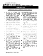
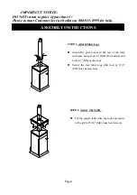
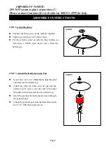
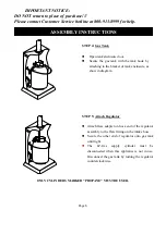
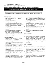
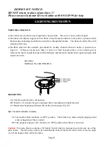
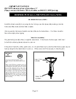

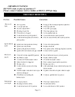

IMPORTANT NOTICE:
DO NOT return to place of purchase !!!
Please contact Customer Service hotline at 800-913-8999 for hel
p
27
30
29
28
22
14
13
25
26
24
23
19
21
20
17
18
6
16
7
8
15
11
12
10
9
5
3
4
1
2
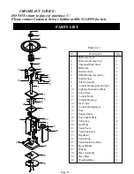
PARTS LIST
Parts List
Description
Reflecotor Nut
Reflecotor Dome Cap
Threaded Ends Stud
Reflector
Emitter Grid
Main Burner Assembly
Emitter base
Pilot Assembly
Control Housing Front Panel
Lighting Instruction Plate
Logo Plate
Control Knob
Control Housing
Gas Valve
Control Husing Base
Post
Square Table
Post Socket Plate
Table Leg
Gas Hose
Tank Cover
Tank Enclosure
Regulator
Tank Hook
Tank Enclosure Door
Door Handle
Wheels
Base Assembly
Base Plate
Weighted Base
No.
1
2
3
4
5
6
7
8
9
10
11
12
13
14
15
16
17
18
19
20
21
22
23
24
25
26
27
28
29
30
Qty
1
1
1
3
1
1
1
1
1
1
1
1
1
1
1
1
1
1
4
1
1
1
1
1
1
1
1
1
1
1
Page 16